Article
This Is Why DACs Produce Ultrasonic Output
Images, oversampling, noise shaping and clock feedthrough, and what they do to the analogue stage after the DAC, by Thorsten Loesch.
Original title: Why DACs Produce Ultrasonic Output
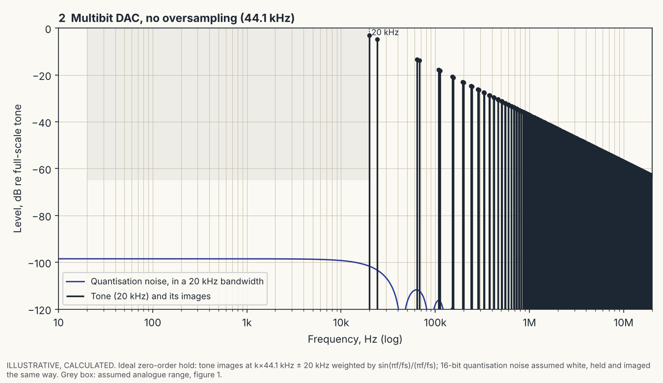
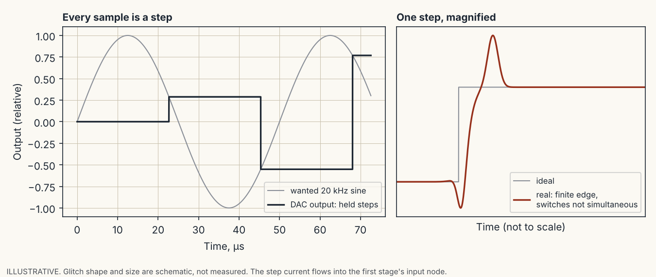
DACA DAC does not output a smooth waveform. It outputs one value per sample period and holds it, so the raw output is a staircase. A staircase is the wanted signal plus copies of it, called images, mirrored around the sample rate and around every multiple of it. For CD at 44.1 kHz a 20 kHz tone therefore also appears at 24.1 kHz (44.1 − 20), at 64.1 kHz (44.1 + 20), at 68.2 kHz (88.2 − 20), and so on without end. The hold gives these images a roll-off of sin(πf/fs) / (πf/fs), and nothing more. At 20 kHz that is 3.2 dB down, at 24.1 kHz 4.8 dB down, so the first image of a 20 kHz tone is only about 1.6 dB below the tone itself (calculated from the formula for an ideal hold; real DACs differ in detail).
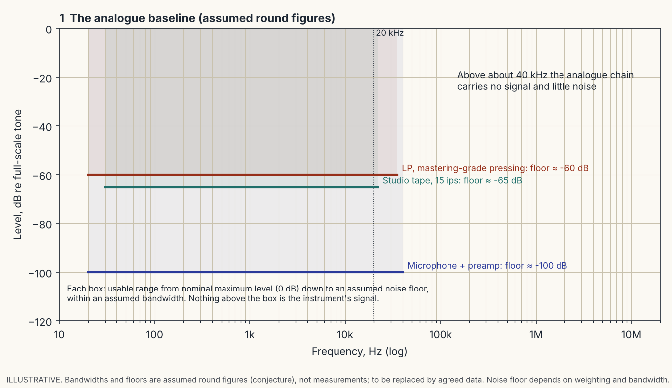
To see what that means for an analogue stage, start from the analogue sources the DAC replaces. A microphone and preamp, a studio tape and an LP carry signal to perhaps 20 to 40 kHz and a noise floor somewhere between about −60 and −100 dB. Above that, nothing. The graphs in this article use one common frame: frequency from 10 Hz to 20 MHz in decades, level from 0 to −120 dB. Where a graph shows a grey box, that is the analogue range of the first figure.
Which of these products matter is decided by the ear, not by the spectrum alone: signal fidelity and audible fidelity overlap only weakly. The position behind that is set out in my position paper The Audio Heretick’s Progress.
Oversampling is a trade, not a cure
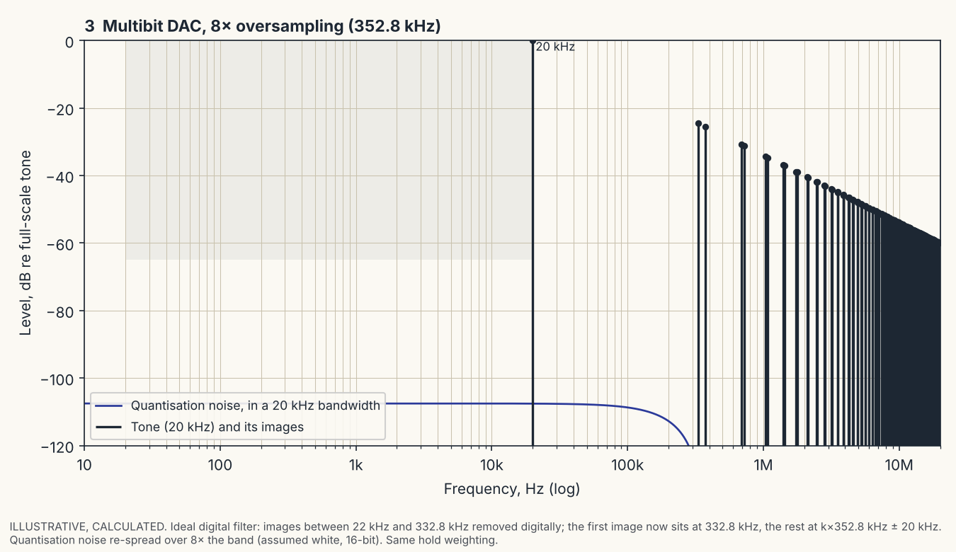
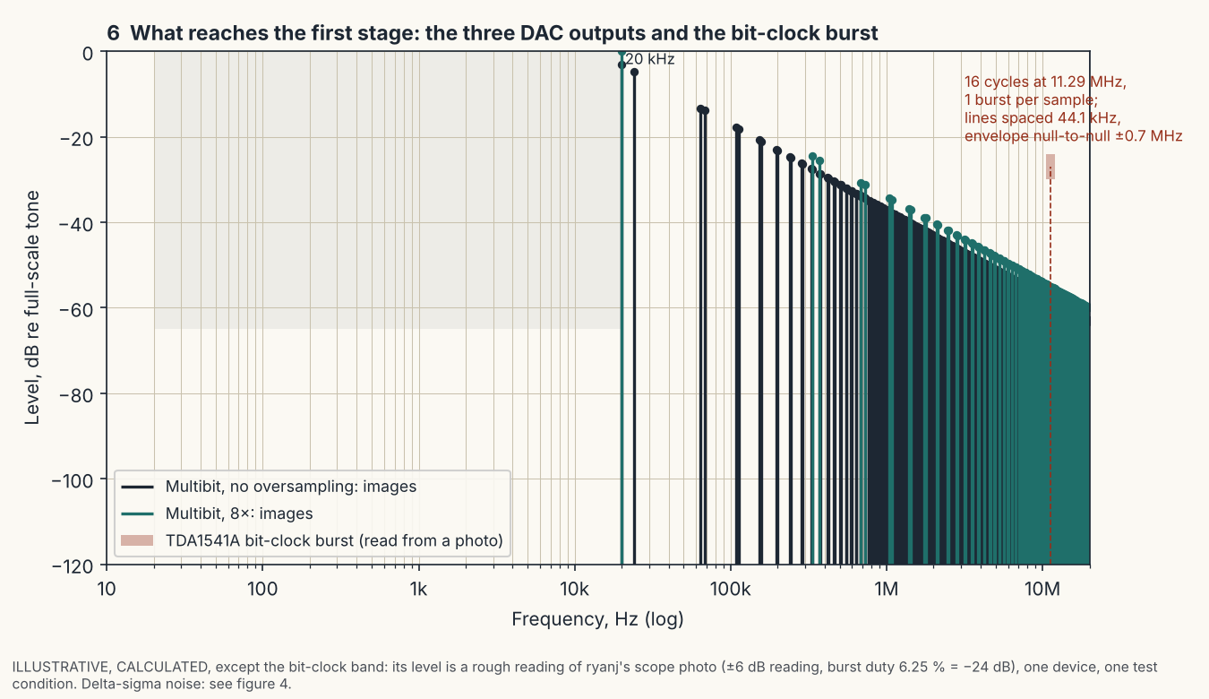
Oversampling is often described as removing the images. It does not. An oversampling digital filter computes new sample values in between the original ones, at N times the rate, and the DAC then holds each of those. The output is still a staircase, only a finer one, and a staircase always carries images. What changes is where they are: the images that sat at multiples of 44.1 kHz are replaced by images at multiples of N × 44.1 kHz. The digital filter deletes the copies nearest the audio band, but the DAC creates a new set at the higher rate. With 8× oversampling (352.8 kHz) the first image of a 20 kHz tone moves from 24.1 kHz to 332.8 kHz (8 × 44.1 − 20).
What it buys is an easier analogue filter. Without oversampling the filter must pass 20 kHz and stop 24.1 kHz, a very steep slope. With 8× it must pass 20 kHz and stop 332.8 kHz, which a gentle low-order filter can do.
What it costs is that the first stage after the DAC, before any filter can act, now sees its images at 332.8 kHz instead of 24.1 kHz. Two things change at the same time.
- Level. The hold attenuates the higher image more. For an ideal hold the 332.8 kHz image is about 24 dB below the tone, against 1.6 dB at 24.1 kHz (calculated; the difference is about 23 dB). That part is a gain.
- Loop gain. A feedback stage is only as linear as its loop gain at the frequency of the content. As an illustration, take an op-amp with a 10 MHz gain-bandwidth product used at unity noise gain. Its loop gain is about 415 (52 dB) at 24 kHz and about 30 (30 dB) at 333 kHz, so about 22 dB less. The demand for slew rate also rises, about 1.4 times for the same content (calculated).
For images produced by the hold, the two effects are of similar size, so that is a trade whose sign depends on the circuit. For content the hold does not attenuate (clock feedthrough, switching glitches, shaped noise, see below) the level does not fall, but the loop gain still does, and then the trade goes the other way. Oversampling is neither good nor bad in itself. It moves a problem from the filter to the first stage.
Delta-sigma moves the error, it does not remove it
A converter with one bit, or a few, can produce only a handful of output levels, so each sample is wrong by a large amount, the quantisation error. Delta-sigma noise shaping does not make the error smaller. It changes where the error falls.
An analogy that stays true: a shopkeeper has only whole coins, so every customer gets change that is a little wrong. A careful shopkeeper writes down the fraction still owed and adds it to the next customer’s change, and the next, and the next. Any one customer may be a little over or under, but over a long run of customers the account balances. The error has not gone; it has been spread over time so that it averages out. In a converter the same bookkeeping, run millions of times a second, pushes the error to high frequencies, where it is not audible and where a filter can remove it. The audio band ends up much cleaner and the region above it much dirtier. The total amount of error actually goes up.
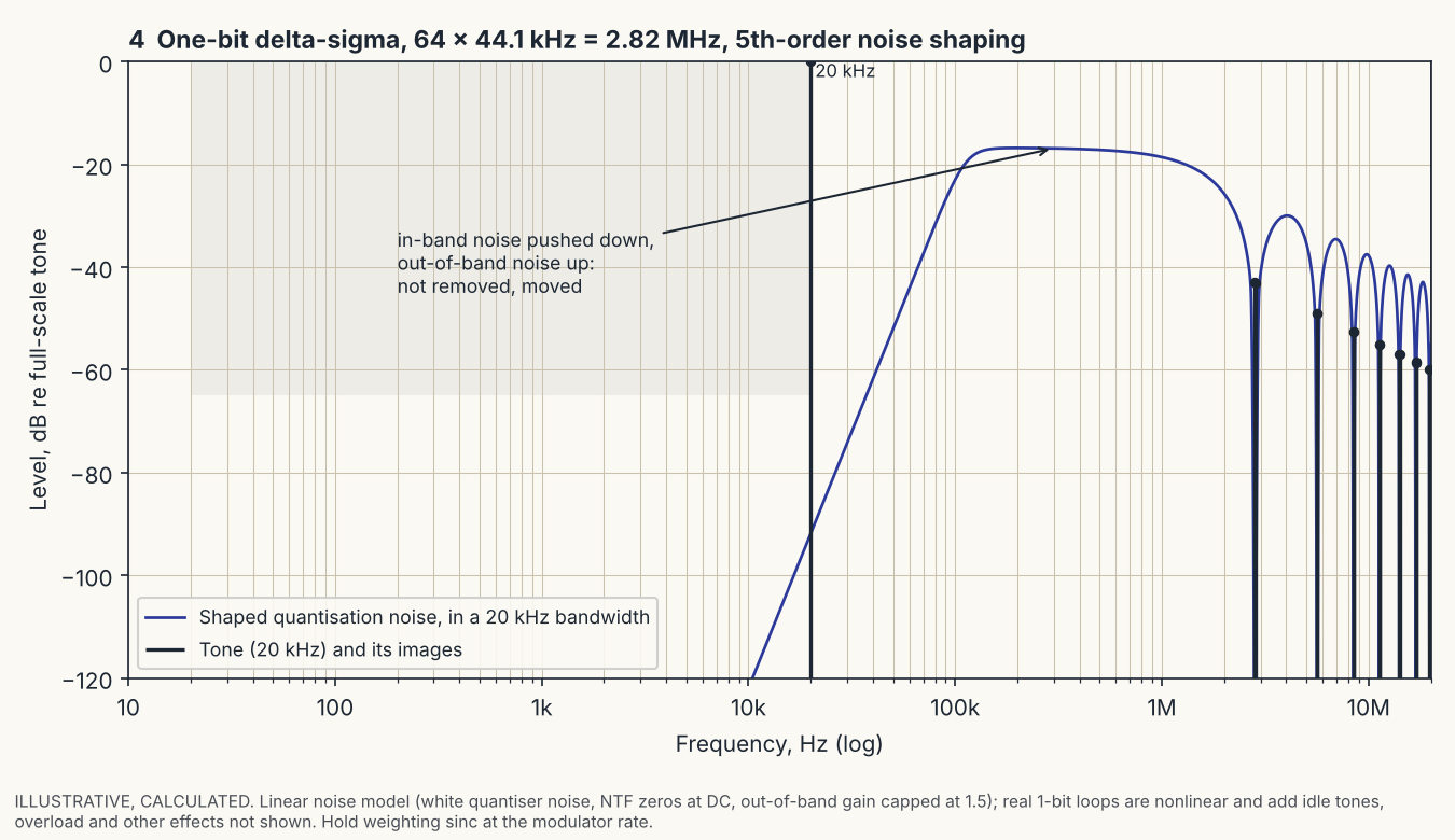
So the output of such a DAC is a fast pulse train, and the audio is its low-frequency average. For the example in figure 4, a one-bit modulator at 64 × 44.1 kHz = 2.82 MHz with fifth-order shaping, the calculated shaped noise reaches about −17 dB relative to a full-scale tone, in a 20 kHz bandwidth, at around 200 kHz, against about −92 dB at 20 kHz. This comes from a simplified linear noise model with assumed parameters; real modulators differ, and I do not have data for any specific chip. The point stands without the numbers: the stage after a delta-sigma DAC meets large high-frequency content that a multibit DAC does not produce, before the filter has acted.
Multibit DACs: edges and clock feedthrough
A current-output multibit DAC changes its output current in a step at every sample. The step is not clean. The switches for the different bits do not change at exactly the same instant, and the edge has a finite speed, so a transition carries a spike or glitch whose size depends on the code before and after it. The worst case is usually the transition where the most significant bit changes and all the others change the opposite way. In an I/V stage the current lands directly on the input of the amplifier, where there is no filter yet.
A second source is feedthrough. A clock or logic signal inside the chip couples into the output through stray capacitance and through the shared substrate, and in CMOS parts through capacitance in the bit switches themselves. The size and spectrum depend on the specific part and are normally not in any datasheet.
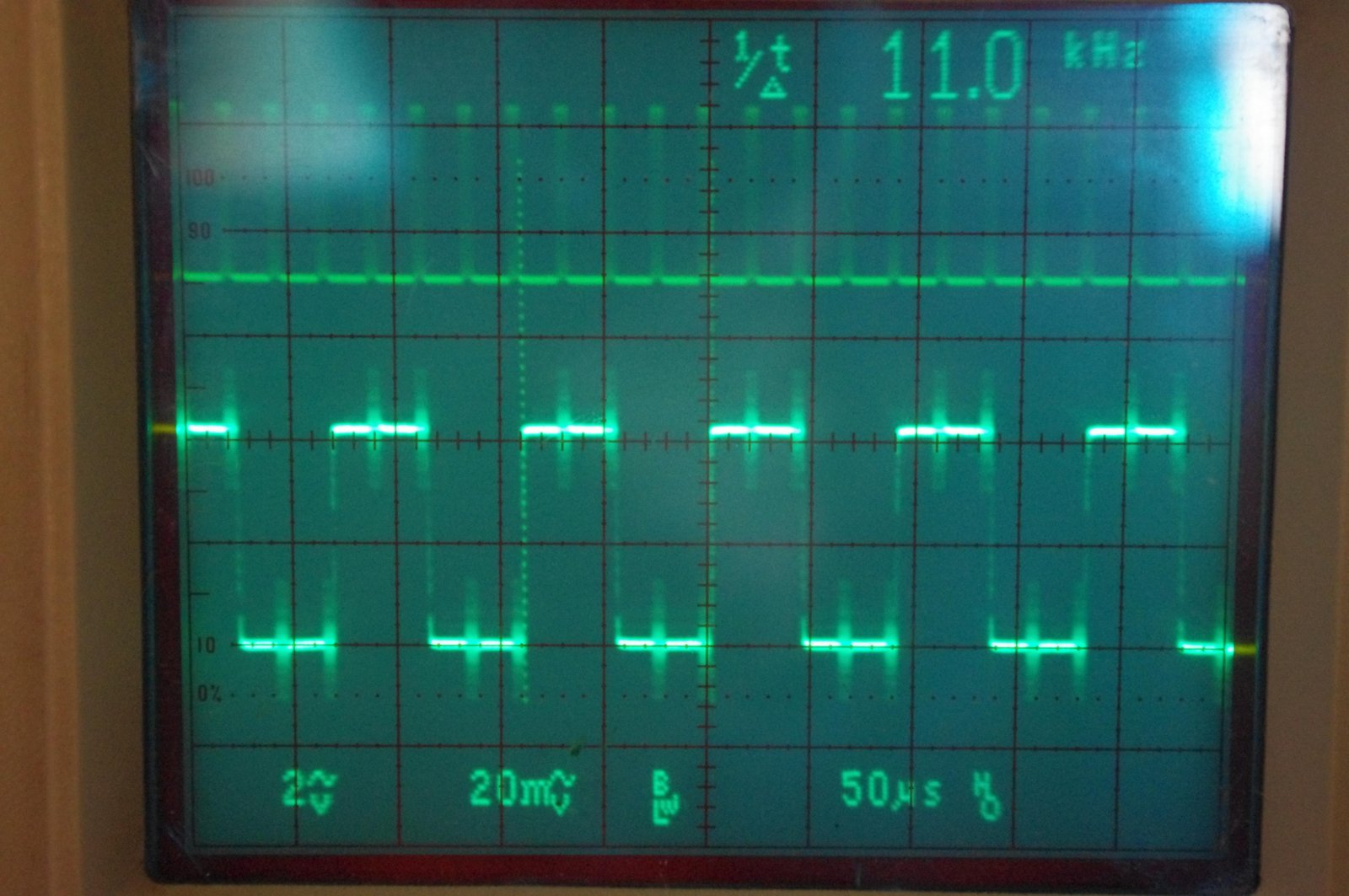
The photograph below is a measurement of this on a TDA1541A, a classic multibit chip with BCK, WCK and DATA inputs but no master clock input. In simultaneous mode the bit clock arrives as one burst of 16 cycles per sample at 11.2896 MHz (256 × 44.1 kHz), then stops. The output is a full-scale 11.025 kHz square wave. The clock bursts are visible on the output at the edges and on the flat parts.
Reading the photo, the spikes reach roughly a third to a half of the square-wave amplitude. That is a rough figure with an uncertainty of about a factor of two, from an analogue scope with limited bandwidth, one device and one test condition. A burst lasts 16 / 11.2896 MHz = 1.42 µs out of a sample period of 22.7 µs, a duty cycle of about 6 %. Repeating once per sample, it should show as a spectrum around 11.29 MHz with lines spaced at 44.1 kHz and an envelope whose first nulls lie about 706 kHz either side (calculated). A spectrum analyser plot would replace these inferences. At 11.29 MHz the 10 MHz GBW op-amp used above has a loop gain of about 1, so for this content an I/V stage like that runs effectively without feedback.
I have no measurement of the equivalent effect in other DAC types, and whether it is also present in a given CMOS part is a matter for a spectrum analyser, not for assumption.
What the ultrasonic content does to an analogue stage
Every source above, images, shaped noise, clock feedthrough, is a PTS: potential trouble source. A technical feature that can cause audible fidelity impairment while staying invisible to the usual FOMs, unless the design addresses it. The Audio Heretick's Progress: the FOM and PTS →: invisible to an audio-band THD+N figure, harmless if the design deals with it, audible if it does not.
An op-amp stage with feedback is only linear while the feedback has enough loop gain to hold its two input terminals at the same voltage. Loop gain falls with frequency and reaches 1 (0 dB) at the amplifier’s unity-gain frequency. For ultrasonic content the amplifier therefore corrects little or nothing, and its input pair is exposed to whatever error voltage the fast content creates. In an I/V converter the DAC’s steps arrive straight at that input.
A bipolar differential input pair is linear only for a small differential voltage, in the order of tens of millivolts (a few multiples of the thermal voltage, about 26 mV at room temperature). Beyond that the pair is overdriven: its output current stops following the input, the stage slew-limits, and for a moment the amplifier runs without feedback and then has to recover. This is the transient intermodulation distortion (TIM) described in section 2. The event is triggered by content that is itself inaudible, and what is heard is its effect in the audio band.
The usual check, slew rate against the slew demand of a full-level 20 kHz sine, gives a reassuring but irrelevant answer. A FOM: figure of merit. A single number, such as THD+N, SINAD or jitter in picoseconds, used to sum up signal fidelity, with the claim that a better number means better sound. It relates to audible fidelity only at the extremes. The Audio Heretick's Progress: the FOM → again: one number that answers the wrong question. A 20 kHz sine of 1.41 V peak (1 V RMS) needs only 2π × 20 kHz × 1.41 V ≈ 0.18 V/µs. The demand comes from the ultrasonic steps and edges, not from the audio sine.
Slew limiting is not the only mechanism. Any non-linearity mixes ultrasonic components with each other. Two components at 45 kHz and 50 kHz passing through a second-order non-linearity produce a difference product at 5 kHz, which is in the audio band. The ultrasonic content is not audible; the demodulated product is. An inaudible signal fidelity impairment turned into an audible one, and invisible to a THD measurement made with a single audio-band sine.
This is why the op-amp matters at a DAC output. A part whose input stage stays linear for a larger differential voltage, with high slew rate and bandwidth, is less likely to be overloaded. FET-input op-amps are, in my experience, the better choice here than the classic bipolar-input types such as the NE5532 and NE5534: a junction-FET input pair tolerates a larger differential input before it overloads. This is a tendency, not a rule. Not every FET-input part is fast, and some bipolar parts are fast, so the datasheet alone does not settle it; noise-load tests and listening do. A valve stage after a suitable low-pass filter sidesteps the question, because it has no loop gain to run out of and its input range is measured in volts.
How much distortion matters?
A single distortion figure is a FOM: figure of merit. A single number, such as THD+N, SINAD or jitter in picoseconds, used to sum up signal fidelity, with the claim that a better number means better sound. It relates to audible fidelity only at the extremes. The Audio Heretick's Progress: the FOM →, and says little unless the spectrum is known. The ear itself generates harmonics. In the experiments of Patterson (1969), quoted in my article on single-ended valve amplifiers, a pure 200 Hz tone at 94 dB SPL produces harmonics in the ear at 400, 600, 800, 1000 and 1200 Hz with levels of 84, 76, 70, 66 and 60 dB. That is a fall of about 12 dB per octave, equivalent to roughly 32, 12.6, 6.3, 4 and 2 per cent, and so more than 30 per cent second harmonic. Yet the tone is heard as pure. If the equipment’s own distortion has the same smoothly falling spectrum and is clearly lower in level, the ear and brain mask it. That is the basis for the statement in that article that, under certain conditions, a measured distortion of several per cent can be inaudible. In the terms of Stage 2: a signal fidelity impairment, but an audible, neutral or even preferred one, not an objectionable one. It is not a claim that any 10 per cent distortion is inaudible.
What is not masked is distortion without that structure: odd-order and high-order products, and intermodulation, especially with many instruments sounding together. Once more than about twelve independent sine waves are present, intermodulation dominates over harmonic distortion. Closely spaced sidebands from high-order products sound “dirty” rather than distorted.
For a DAC output stage this sets the target. The aim is not zero THD, the FOM: figure of merit. A single number, such as THD+N, SINAD or jitter in picoseconds, used to sum up signal fidelity, with the claim that a better number means better sound. It relates to audible fidelity only at the extremes. The Audio Heretick's Progress: the FOM →, but audible fidelity. A modest amount of low-order harmonic and intermodulation distortion, of the kind a triode stage produces, is a minor issue. The products to avoid are the others: slew-limiting events, overload recovery, and ultrasonic content demodulated into the audio band by an input stage that was never designed to see it.
No magic, only trades
- Negative feedback reduces distortion where there is loop gain. Loop gain runs out at high frequency, exactly where the DAC output has its fast content.
- Oversampling relaxes the analogue filter. It moves the images to higher frequencies, where they meet less loop gain in the first stage.
- Noise shaping lowers the noise in the audio band. It raises the total error power and puts it above the audio band.
- A valve stage with no feedback has no loop gain to run out of. It has its own costs: output impedance, power, size, ageing.
Each of these is a choice with a price. Claims that one of them simply removes a problem are incomplete.
The output stage’s job is to keep the illusion intact (Stage 4); demodulated ultrasonic grit is one of the surest ways to break it.
See also
This article started as a set of 2026 notes in Thermionic Valve Analogue Stages for Digital Audio, which shows what valve stages behind a DAC look like in practice.