
Article
Why All Digital Filters Are Wrong
Ringing, pre-ringing, images and the ear: what a digital filter in a DAC trades, and what to aim for, by Thorsten Loesch.
DACDigital FiltersAll digital filters for audio are wrong. All of them, including the “no filter” option.
They differ only in how they are wrong. Every digital filter adds its own error signature, either in time (how a transient comes out) or in frequency (what is left of the ultrasonic images, how flat the treble is). Usually both. The lower the sample rate, the more these errors matter, so the most common source of all, CD at 44.1 kHz, is hit hardest.
Where there is a difference, there is a preference. Every filter is a signal fidelity impairment; whether it becomes an audible one, and whether that is preferred or objectionable, is decided by the ear, not the specification (Stage 2). Listeners prefer different filters for different reasons, including what they have learned to hear as “hifi”. But with enough listening and a little thinking about how the ear works, we can say what a sensible filter should aim for.
Why the ear, and not the measurement, is the reference here, and why signal and audible fidelity only weakly overlap, is set out in my position paper The Audio Heretick’s Progress.
What a digital filter is
A digital filter is a delay line. The signal is passed along a chain of one-sample delays, and at each step a copy is taken off, a tap. Each tap is scaled by its own coefficient, positive or negative, and all of them are added up. That sum is the output.
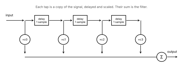
The number of taps sets how long the filter “remembers” a sample: 32 taps at 44.1 kHz last 0.73 ms; 16k taps (16,384) last 0.37 seconds, about 186 ms on either side of the transient for a linear-phase filter. A digital reverb unit is built from exactly the same parts, which is worth keeping in mind.
Ringing, and why no filter fixes it
Take a square wave and remove everything above some frequency. What comes out is not a slightly softer square wave, but one that overshoots and rings at every edge. This is the Gibbs phenomenon, named after J. Willard Gibbs. With only the fundamental left, the square wave becomes a sine wave. With more harmonics it gets closer, but the overshoot never goes away: it stays at about 9 % of the step, however many harmonics we keep.
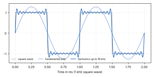
No filter restores the perfect square wave. A digital filter only decides what shape the error takes, and where in time it sits.
Three ways to be wrong
Here are three typical choices for a DAC at 44.1 kHz, in time and in frequency.
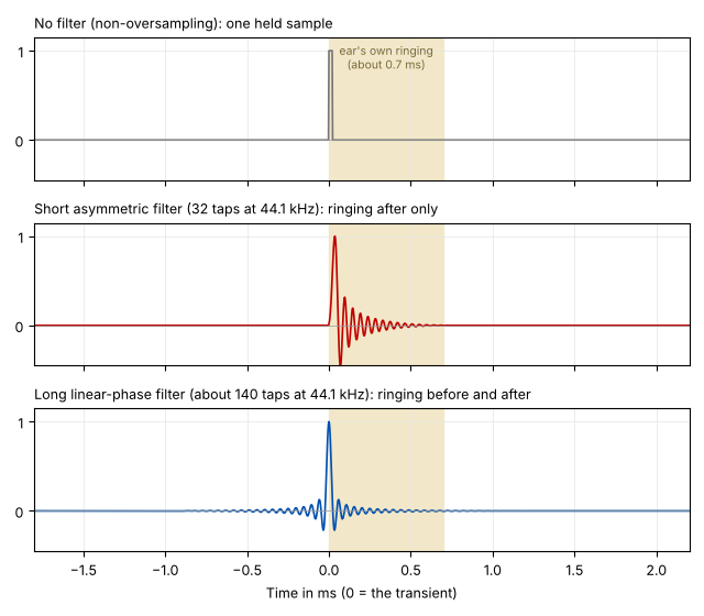
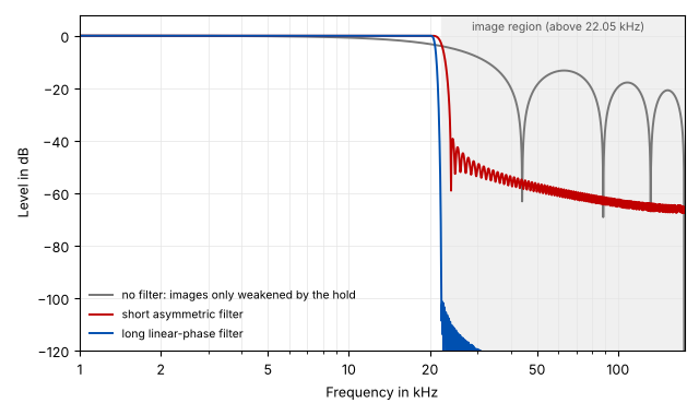
No filter (non-oversampling). Each sample is simply held until the next. In time this is as clean as it gets: no ringing at all. In frequency it is the worst: the treble is already down about 3 dB at 20 kHz, and the ultrasonic images above 22 kHz are only weakened by a few dB. They go straight into the analogue stage that follows. Why that matters is the subject of This Is Why DACs Produce Ultrasonic Output.
A long linear-phase filter, the usual choice in DAC chips. Excellent in frequency: flat to 20 kHz, images removed by 100 dB or more. These are the FOM: figure of merit. A single number, such as THD+N, SINAD or jitter in picoseconds, used to sum up signal fidelity, with the claim that a better number means better sound. It relates to audible fidelity only at the extremes. The Audio Heretick's Progress: the FOM → on the DAC chip’s datasheet, and they are excellent. They say nothing about how long the filter rings, or that half of it comes before the transient. Pre-ringing is a PTS: potential trouble source. A technical feature that can cause audible fidelity impairment while staying invisible to the usual FOMs, unless the design addresses it. The Audio Heretick's Progress: the FOM and PTS →. In time it rings, and it rings symmetrically: as much before the transient as after it.
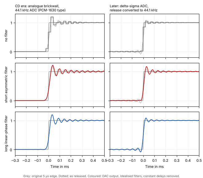
A short asymmetric filter. Few taps, and arranged so all the ringing comes after the transient. It removes the images much better than no filter, though nowhere near as completely as a long one. In time it is finished in well under a millisecond, and nothing happens before the transient. The price in time is excess phase: near the top of the band it delays the treble more than the bass. In the example below, the delay rises from about 28 µs in the bass to about 100 µs at 20 kHz, and an edge comes out displaced by a few µs as well as slowed.
What the ear does with a transient
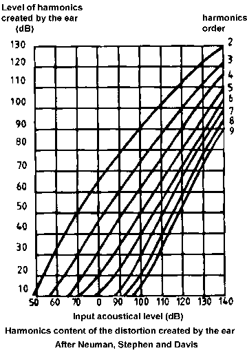
The ear is a remarkable system: an enormous dynamic range, a bandwidth of about 1:1000, and a fine sense of timing. But it is not a microphone. It has its own behaviour, and that behaviour hides some things that are, objectively, distortion: signal fidelity impairments that never become audible ones. Masking of harmonic distortion has been documented since at least the 1950s. It is reasonable to expect that ringing on transients is masked to some degree too.
The ear’s time resolution for the onset of a transient may be as small as 5 µs. The exact limit is debated; work by Dr Peter Lennox of Derby University suggests a median of 13 to 18 µs.
Two facts matter here.
First, the ear rings by itself. The eardrum and the small bones behind it (malleus, incus, stapes) are a mechanical system, and after a transient it rings for about 0.5 to 0.7 ms (Razavi, Ravicz et al., 2016). This ringing comes after the transient. There is no pre-ringing in nature: nothing makes a sound before it happens.
Second, ringing that falls inside the ear’s own ringing time, and comes after the transient, is merged into the transient and is not heard as something separate. Pre-ringing is not masked this way, and neither is ringing that lasts much beyond the ear’s own.
Further out lies the precedence (Haas) window. Reflections arriving within a few milliseconds of a sound are merged with it into one event; later ones start to be heard as echo or reverberation. The exact limit is debated, and it is longer for speech and music than for clicks.
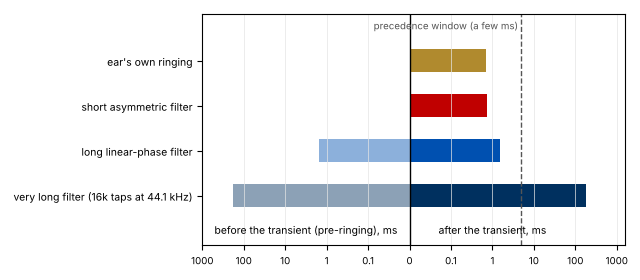
How long does a long filter actually ring? Its ringing decays towards the ends. For a typical 16,000-tap filter at 44.1 kHz, the ringing stays above -40 dB for about 1.5 ms either side of the transient, above -60 dB for about 15 ms, above -80 dB for about 84 ms and above -100 dB for about 168 ms (calculated). At which of these levels it stops mattering is open to debate. What is not debatable is that half of it comes before the transient, which nothing in nature does, and that most of it lasts far longer than the ear’s own ringing can hide.
So what should a filter aim for?
Following the ear, a digital filter that should not materially change how music is perceived needs two things:
- No pre-ringing. All of its ringing comes after the transient.
- Finished within the ear’s own ringing, about 0.7 ms.
The criterion is audible fidelity, not signal fidelity: the short filter measures worse on every datasheet FOM: figure of merit. A single number, such as THD+N, SINAD or jitter in picoseconds, used to sum up signal fidelity, with the claim that a better number means better sound. It relates to audible fidelity only at the extremes. The Audio Heretick's Progress: the FOM →, and is the better choice.
At 44.1 or 48 kHz that means an asymmetric filter of no more than about 32 taps. At 88.2 or 96 kHz, no more than about 64. Filters that need more than a few milliseconds to complete their response, more than about 220 taps at 44.1 kHz, have the potential to be audible as an alteration.
The price is paid in frequency: such a filter cannot remove the images as completely as a long one. But it removes far more than no filter, and it keeps the time behaviour within what the ear hides by itself. That is the trade I prefer.
Higher sample rates help
At 88.2 or 96 kHz the images start far above the audio band, so the filter can be gentle and its cutoff can sit well above 20 kHz. A gentle filter is a short one, and its ringing is shorter and at a higher frequency. The trade between time and frequency gets easier.
There is a second reason: the edge itself. A real transient rises in a finite time, and to keep its shape a system needs a bandwidth of roughly 0.35 divided by that rise time. An edge rising in 5 µs needs about 70 kHz of bandwidth, and with room for a filter, a sample rate of around 200 kHz. An edge rising in 20 µs needs about 17.5 kHz, so a sample rate of a little over 50 kHz. At 44.1 kHz we have no good option: with the brickwall filter, the edge is slowed and rings, and with a minimum-phase or analogue brickwall it is also displaced in time by the filter’s excess phase; without it, the part above 22.05 kHz aliases back into the audio band. A good middle ground is 88.2 or 96 kHz.
Most recordings, high-resolution ones included, have already passed through filters in the recording chain. An analogue filter cannot be linear-phase, so where the brickwall sat in the analogue domain ahead of the ADC, as in early digital recording, the edges were already displaced at the source. Modern oversampling ADCs do the brickwall digitally, usually as a long linear-phase filter. Time-domain errors add up along the chain, recording and playback, and cannot be removed afterwards unless their exact nature is known. By the time it reaches our DAC, the recording is already a long way from the original event: fidelity to what? (Stage 3) And the chain is long. A typical recording passes through an analogue anti-alias filter, the converter’s own decimation filter, often a sample-rate conversion down to 44.1 kHz for release, which is another brickwall, and only then reaches the playback filter in our DAC. Few studios use the best converters available, and fewer still record at sample rates high enough for gentle filters. Every one of these filters leaves its mark on the edge, and the marks add up. The playback filter is only the last link, but it is the one we can choose.
Everything is a trade
No filter, long filter, short filter: each is wrong in its own way. The choice is not between right and wrong, but between which error we can live with. Mine is the one that keeps time like the ear does, and accepts a little less image rejection for it.
A DAC cannot reproduce the recording perfectly; no part of the chain can. Its job is to keep the illusion intact (Stage 4), and a filter that keeps time like the ear does serves it.
This article is a rewrite of an iFi audio Tech Note I wrote in 2018, with the product description and marketing removed.