
Article
This Is How to Put Valve Stages Behind a DAC, Explained
The 1999 article for the London Live DIY Hifi Circle, with the 2010 comments and new 2026 notes on ultrasonic DAC output and op-amp stages.
Original title: Thermionic Valve Analogue Stages for Digital Audio
DACDAC With TubesPreface and update
The bulk of this article is retained from the original, written in 1999 and published worldwide first in valve 2/2000.
It is perhaps to the credit of the early revival of DIY Valve Audio as embodied by “Valve” and “Sound Practices” that this article (which owes so much to both magazines and the communities that sprang up around them in the early days of the internet) has remained in demand and is still occasionally referenced.
Reading one’s own writings with a decade distance is often an interesting experience. Yet I feel that overall this article has stood the test of time well and remains relevant in today’s world. In the days I wrote the original article I was working by day on doomsday scenarios where all computers would crash on the first of Jan 2000 and destroy civilisation as we know it or worse and how to stop it from happening (that one went with such a fizzle, I expected more after all that build-up).
The article was written quite aggressively, as it was originally published in an extremely limited circulation, privately published newsletter. I let it stand as was for publication nearly a year later worldwide and decided to do so again a decade later. On occasion a spade must be called a spade, not in misguided political correctness a “wood and metal digging instrument of limited application”.
Valve Amplifiers were a comparably rare sight at hifi shows and DACs or CD players with valves could be compared to rocking horse droppings. Nowadays you cannot swing a cat or throw a brick in any hifi exhibition without it destroying several valve amps and so-called valve or valve CD players in the process. Of course the “valve” CD players and DACs rarely are true valve units; usually they just contain a valve buffer after a thoroughly conventional and often not so well designed solid state analogue stage. Still, one has got to give points for effort).
I have taken the liberty to insert comments to account for a world that has much changed in the intervening decade with 9/11 and 7/7, al Qaeda, the long awaited sequel to Operation Desert Storm, the infamous Taliban prowling the streets of the UK and the RIAA mass-suing its customers, the rise and fall of the Piratebay plus a global economical crisis which would not have looked bad as the Y2K disaster that never arrived.
I have cleaned up some spelling mistakes and the odd bit of grammar. I also append a circuit for voltage output DACs not present in the original article, which in my current experience may be a better choice than the one presented originally, which is however retained. All later additions are presented in italic letters (like this section) compared to the original text.
1. Introduction
In the last decade of the 20th century the whole issue of how to interface the silicon nastiness of CD players and digital to analogue converters to valve equipment has received extensive coverage in the audiophile and DIY audio press. Much polemic has issued forth and has since died down. A number of companies have even introduced add on Valve Stages claiming them to be “the missing links” and the like and have since disappeared again from the market. This brief article shall not concern itself with the polemic surrounding the issue, or with specific criticism of many implemented solutions.
Nor shall we discuss the inherent futility of attempting to “reform” or “improve” by introducing valves, a digital audio format which not only suffers from enough build in limitation as to make true “High Fidelity” inherently impossible and for which the vast majority of recordings not even make use of the available quality. Nor shall the issues of massively incompetent digital design (clock jitter, PSU decoupling, managing of RF Noise and so on) in almost all commercially available equipment be discussed here in length.
Despite being the decade of so-called “CD-Quality” lossy compression and the iPod, the decade that has passed since the original article has also brought acceptable audiophile sound from CD much, much closer for average audiophiles and into the grasp of those who do not mind paying very large amounts.
Experiments that I carried out since have shown that both using unusual solutions in traditional engineering as well as “guerrilla engineering” can produce a much “reformed” and “improved” sound quality from CD. At the time of writing the original article I had already been experimenting for some time using DACs without digital filtering, finding them capable of exceptional performance in some areas, yet in need of improvement in others, something on which I have spend quite some time on, with some success, if I may say so.
Before continuing with this Article the august reader is advised to make herself or himself comfortable with the underlying principles of Digital Audio and CD player in special as no further consideration will be given to this topic.
The article covering CD on the “How Stuff Works” site is a good choice to get a quick initial overview of the subject and is recommended. The Wikipedia Entry for “CD player” may also help.
Instead we shall concern ourselves only with delivering of the however compromised output Signal from the Digital to Analogue Converter to the Output Jacks with the least amount of further perceived degradation.
Considering this task, the use of Zero Feedback circuits seems almost mandatory almost – using the right configuration of a local feedback loop can sound very good too. This is because with a DAC or CD player we deal with a generator of massive levels of wideband RF noise, which, if used with conventional feedback based circuits will lead to severe levels of inter-modulation distortion. This is easily observable with noise-load testing as much as 1% with leading high end converters and worse for much consumer equipment.
So, having defined the almost absolute need for zero feedback circuits then if our goal is to offer high fidelity without recourse to repeated design iterations and use of expensive superfast, high resolution FFT analysers and noise-load testing, the only readily available devices with an ability to offer low enough distortion levels in zero feedback mode are thermionic valves, most notabene triodes. I have since had the chance to use such high resolution test gear developing a lot of circuitry and still prefer to use triodes.
Why DACs produce ultrasonic output
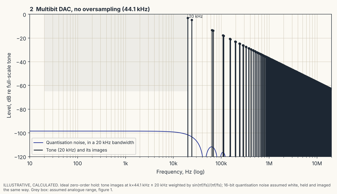
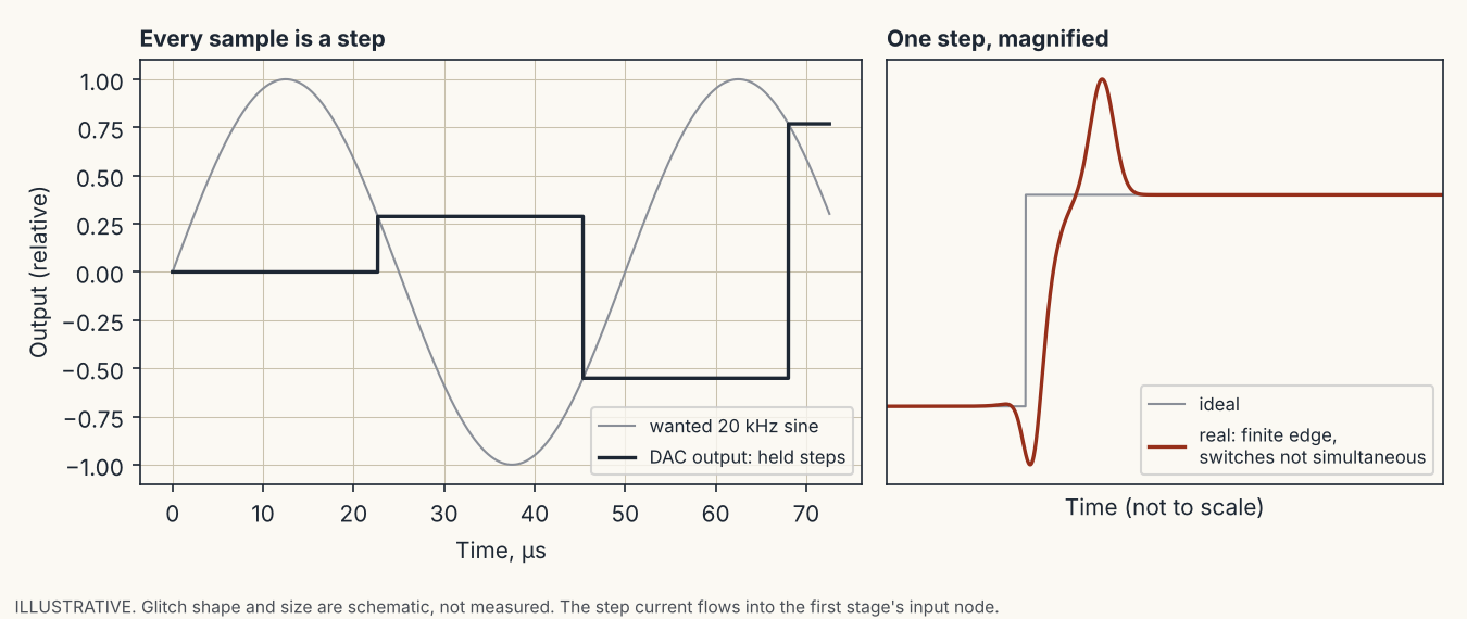
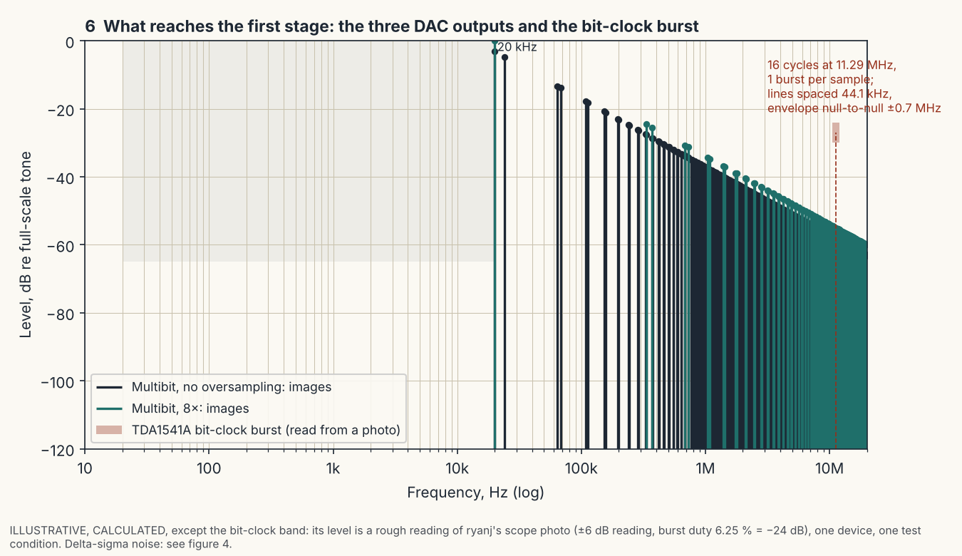
A DAC does not output a smooth waveform. It outputs one value per sample period and holds it, so the raw output is a staircase. A staircase is the wanted signal plus copies of it, called images, mirrored around the sample rate and around every multiple of it. For CD at 44.1 kHz a 20 kHz tone therefore also appears at 24.1 kHz (44.1 − 20), at 64.1 kHz (44.1 + 20), at 68.2 kHz (88.2 − 20), and so on without end. The hold gives these images a roll-off of sin(πf/fs) / (πf/fs), and nothing more. At 20 kHz that is 3.2 dB down, at 24.1 kHz 4.8 dB down, so the first image of a 20 kHz tone is only about 1.6 dB below the tone itself (calculated from the formula for an ideal hold; real DACs differ in detail).
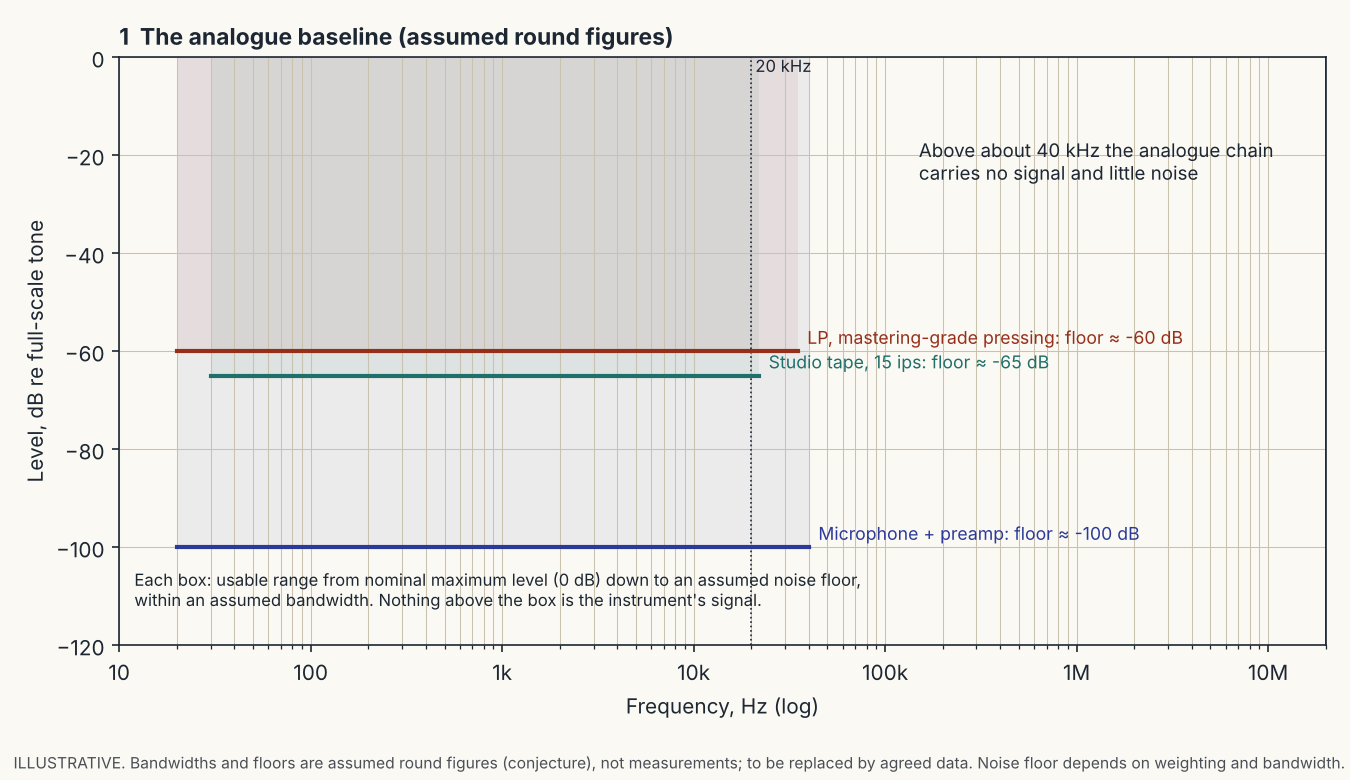
To see what that means for an analogue stage, start from the analogue sources the DAC replaces. A microphone and preamp, a studio tape and an LP carry signal to perhaps 20 to 40 kHz and a noise floor somewhere between about −60 and −100 dB. Above that, nothing. The graphs in this section use one common frame: frequency from 10 Hz to 20 MHz in decades, level from 0 to −120 dB. Where a graph shows a grey box, that is the analogue range of the first figure.
Oversampling is a trade, not a cure
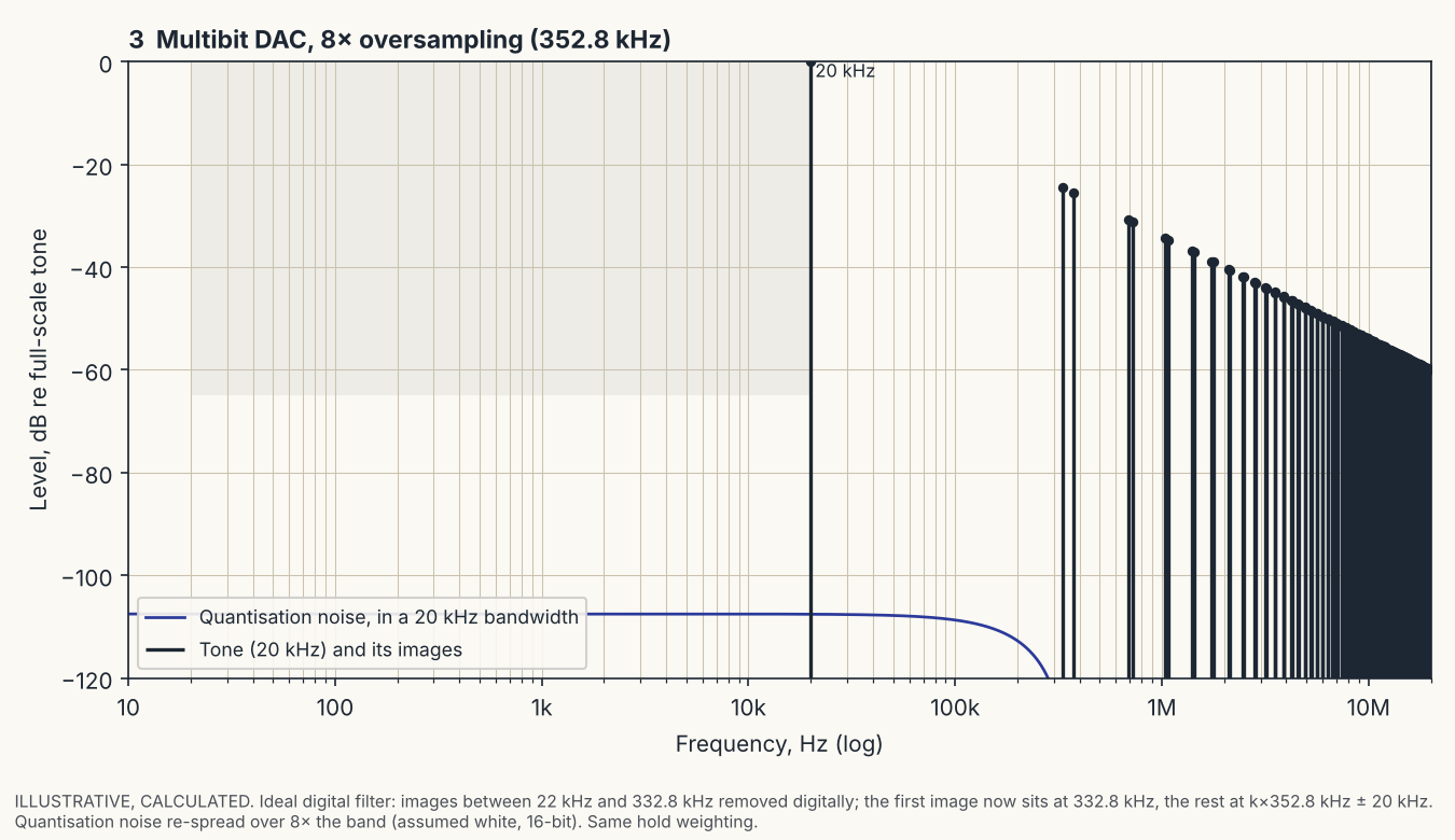
Oversampling is often described as removing the images. It does not. An oversampling digital filter computes new sample values in between the original ones, at N times the rate, and the DAC then holds each of those. The output is still a staircase, only a finer one, and a staircase always carries images. What changes is where they are: the images that sat at multiples of 44.1 kHz are replaced by images at multiples of N × 44.1 kHz. The digital filter deletes the copies nearest the audio band, but the DAC creates a new set at the higher rate. With 8× oversampling (352.8 kHz) the first image of a 20 kHz tone moves from 24.1 kHz to 332.8 kHz (8 × 44.1 − 20).
What it buys is an easier analogue filter. Without oversampling the filter must pass 20 kHz and stop 24.1 kHz, a very steep slope. With 8× it must pass 20 kHz and stop 332.8 kHz, which a gentle low-order filter can do.
What it costs is that the first stage after the DAC, before any filter can act, now sees its images at 332.8 kHz instead of 24.1 kHz. Two things change at the same time.
- Level. The hold attenuates the higher image more. For an ideal hold the 332.8 kHz image is about 24 dB below the tone, against 1.6 dB at 24.1 kHz (calculated; the difference is about 23 dB). That part is a gain.
- Loop gain. A feedback stage is only as linear as its loop gain at the frequency of the content. As an illustration, take an op-amp with a 10 MHz gain-bandwidth product used at unity noise gain. Its loop gain is about 415 (52 dB) at 24 kHz and about 30 (30 dB) at 333 kHz, so about 22 dB less. The demand for slew rate also rises, about 1.4 times for the same content (calculated).
For images produced by the hold, the two effects are of similar size, so that is a trade whose sign depends on the circuit. For content the hold does not attenuate (clock feedthrough, switching glitches, shaped noise, see below) the level does not fall, but the loop gain still does, and then the trade goes the other way. Oversampling is neither good nor bad in itself. It moves a problem from the filter to the first stage.
Delta-sigma moves the error, it does not remove it
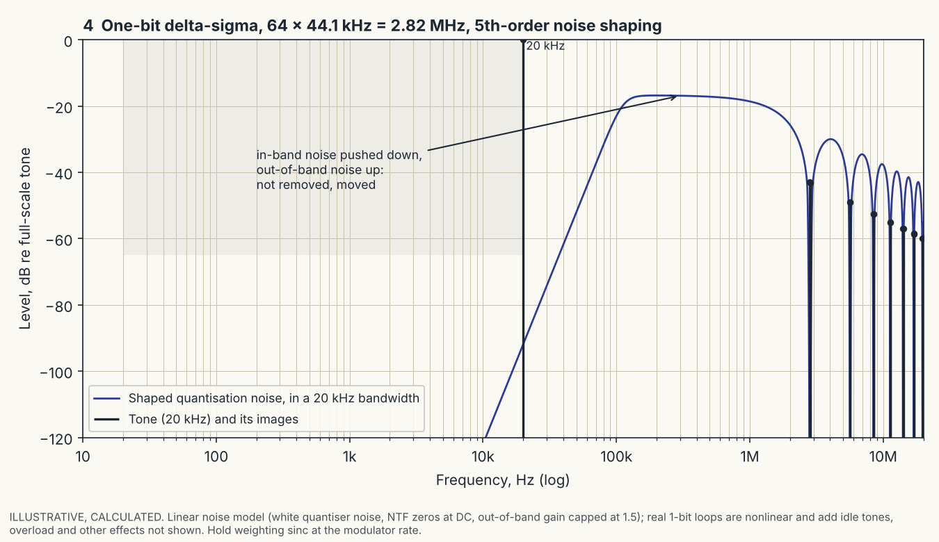
A converter with one bit, or a few, can produce only a handful of output levels, so each sample is wrong by a large amount, the quantisation error. Delta-sigma noise shaping does not make the error smaller. It changes where the error falls.
An analogy that stays true: a shopkeeper has only whole coins, so every customer gets change that is a little wrong. A careful shopkeeper writes down the fraction still owed and adds it to the next customer’s change, and the next, and the next. Any one customer may be a little over or under, but over a long run of customers the account balances. The error has not gone; it has been spread over time so that it averages out. In a converter the same bookkeeping, run millions of times a second, pushes the error to high frequencies, where it is not audible and where a filter can remove it. The audio band ends up much cleaner and the region above it much dirtier. The total amount of error actually goes up.
So the output of such a DAC is a fast pulse train, and the audio is its low-frequency average. For the example in figure 4, a one-bit modulator at 64 × 44.1 kHz = 2.82 MHz with fifth-order shaping, the calculated shaped noise reaches about −17 dB relative to a full-scale tone, in a 20 kHz bandwidth, at around 200 kHz, against about −92 dB at 20 kHz. This comes from a simplified linear noise model with assumed parameters; real modulators differ, and I do not have data for any specific chip. The point stands without the numbers: the stage after a delta-sigma DAC meets large high-frequency content that a multibit DAC does not produce, before the filter has acted.
Multibit DACs: edges and clock feedthrough
A current-output multibit DAC changes its output current in a step at every sample. The step is not clean. The switches for the different bits do not change at exactly the same instant, and the edge has a finite speed, so a transition carries a spike or glitch whose size depends on the code before and after it. The worst case is usually the transition where the most significant bit changes and all the others change the opposite way. In an I/V stage the current lands directly on the input of the amplifier, where there is no filter yet.
A second source is feedthrough. A clock or logic signal inside the chip couples into the output through stray capacitance and through the shared substrate, and in CMOS parts through capacitance in the bit switches themselves. The size and spectrum depend on the specific part and are normally not in any datasheet.
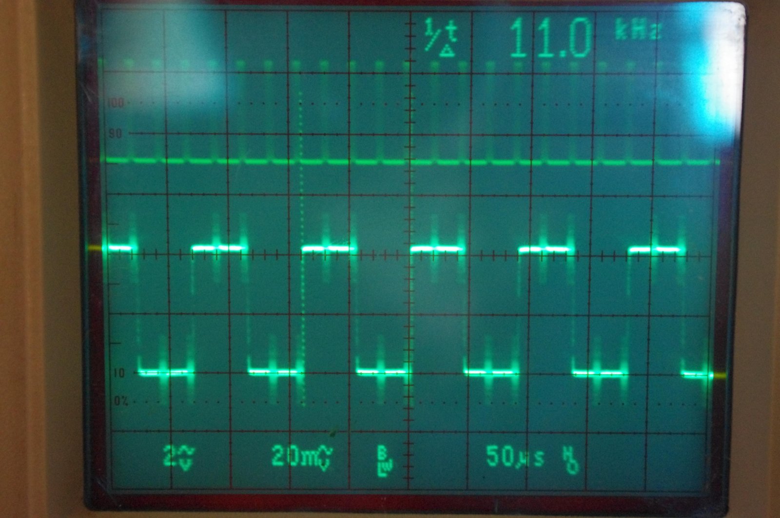
The photograph below is a measurement of this on a TDA1541A, a classic multibit chip with BCK, WCK and DATA inputs but no master clock input. In simultaneous mode the bit clock arrives as one burst of 16 cycles per sample at 11.2896 MHz (256 × 44.1 kHz), then stops. The output is a full-scale 11.025 kHz square wave. The clock bursts are visible on the output at the edges and on the flat parts.
Reading the photo, the spikes reach roughly a third to a half of the square-wave amplitude. That is a rough figure with an uncertainty of about a factor of two, from an analogue scope with limited bandwidth, one device and one test condition. A burst lasts 16 / 11.2896 MHz = 1.42 µs out of a sample period of 22.7 µs, a duty cycle of about 6 %. Repeating once per sample, it should show as a spectrum around 11.29 MHz with lines spaced at 44.1 kHz and an envelope whose first nulls lie about 706 kHz either side (calculated). A spectrum analyser plot would replace these inferences. At 11.29 MHz the 10 MHz GBW op-amp used above has a loop gain of about 1, so for this content an I/V stage like that runs effectively without feedback.
I have no measurement of the equivalent effect in other DAC types, and whether it is also present in a given CMOS part is a matter for a spectrum analyser, not for assumption.
What the ultrasonic content does to an analogue stage
An op-amp stage with feedback is only linear while the feedback has enough loop gain to hold its two input terminals at the same voltage. Loop gain falls with frequency and reaches 1 (0 dB) at the amplifier’s unity-gain frequency. For ultrasonic content the amplifier therefore corrects little or nothing, and its input pair is exposed to whatever error voltage the fast content creates. In an I/V converter the DAC’s steps arrive straight at that input.
A bipolar differential input pair is linear only for a small differential voltage, in the order of tens of millivolts (a few multiples of the thermal voltage, about 26 mV at room temperature). Beyond that the pair is overdriven: its output current stops following the input, the stage slew-limits, and for a moment the amplifier runs without feedback and then has to recover. This is the transient intermodulation distortion (TIM) described in section 2. The event is triggered by content that is itself inaudible, and what is heard is its effect in the audio band.
The usual check, slew rate against the slew demand of a full-level 20 kHz sine, gives a reassuring but irrelevant answer. A 20 kHz sine of 1.41 V peak (1 V RMS) needs only 2π × 20 kHz × 1.41 V ≈ 0.18 V/µs. The demand comes from the ultrasonic steps and edges, not from the audio sine.
Slew limiting is not the only mechanism. Any non-linearity mixes ultrasonic components with each other. Two components at 45 kHz and 50 kHz passing through a second-order non-linearity produce a difference product at 5 kHz, which is in the audio band. The ultrasonic content is not audible; the demodulated product is.
This is why the op-amp matters at a DAC output. A part whose input stage stays linear for a larger differential voltage, with high slew rate and bandwidth, is less likely to be overloaded. FET-input op-amps are, in my experience, the better choice here than the classic bipolar-input types such as the NE5532 and NE5534: a junction-FET input pair tolerates a larger differential input before it overloads. This is a tendency, not a rule. Not every FET-input part is fast, and some bipolar parts are fast, so the datasheet alone does not settle it; noise-load tests and listening do. A valve stage after a suitable low-pass filter sidesteps the question, because it has no loop gain to run out of and its input range is measured in volts.
How much distortion matters?
Distortion figures say little unless the spectrum is known. The ear itself generates harmonics. In the experiments of Patterson (1969), quoted in my article on single-ended valve amplifiers, a pure 200 Hz tone at 94 dB SPL produces harmonics in the ear at 400, 600, 800, 1000 and 1200 Hz with levels of 84, 76, 70, 66 and 60 dB. That is a fall of about 12 dB per octave, equivalent to roughly 32, 12.6, 6.3, 4 and 2 per cent, and so more than 30 per cent second harmonic. Yet the tone is heard as pure. If the equipment’s own distortion has the same smoothly falling spectrum and is clearly lower in level, the ear and brain mask it. That is the basis for the statement in that article that, under certain conditions, a measured distortion of several per cent can be inaudible. It is not a claim that any 10 per cent distortion is inaudible.
What is not masked is distortion without that structure: odd-order and high-order products, and intermodulation, especially with many instruments sounding together. Once more than about twelve independent sine waves are present, intermodulation dominates over harmonic distortion. Closely spaced sidebands from high-order products sound “dirty” rather than distorted.
For a DAC output stage this sets the target. The aim is not zero THD. A modest amount of low-order harmonic and intermodulation distortion, of the kind a triode stage produces, is a minor issue. The products to avoid are the others: slew-limiting events, overload recovery, and ultrasonic content demodulated into the audio band by an input stage that was never designed to see it.
No magic, only trades
- Negative feedback reduces distortion where there is loop gain. Loop gain runs out at high frequency, exactly where the DAC output has its fast content.
- Oversampling relaxes the analogue filter. It moves the images to higher frequencies, where they meet less loop gain in the first stage.
- Noise shaping lowers the noise in the audio band. It raises the total error power and puts it above the audio band.
- A valve stage with no feedback has no loop gain to run out of. It has its own costs: output impedance, power, size, ageing.
Each of these is a choice with a price. Claims that one of them simply removes a problem are incomplete.
Now, how do we interface triode valve circuits to the kind of DAC chips commonly found in consumer digital equipment?
To answer this we must first understand that currently two fundamentally different DAC architectures are being used and that the two different architectures require a fundamentally different approach to analogue stage design. The two DAC architectures in question are multibit and timeslicing DACs.
Let’s look at the technology.
2. Multibit digital-to-analogue converters
The multibit DAC is the classic technology used from the beginning and has a very long history outside digital audio. In most simple terms a multibit DAC contains a number of switches and a resistor network (and some auxiliary circuitry). Each of the switches corresponds to a “Bit” and will switch in a resistor allowing a certain current to be presented on the output of the DAC chip.
If we take the classic Philips TDA 1541 multibit DAC as example, the MSB (most significant Bit) will toggle on or off a Switch which will switch on or off a current of 2mA. With all bits at Zero all switches will be off and the output will be at zero. Switching the MSB on will produce -2mA current and represents basically “digital silence”. Switching all other 15 Switches on will add another -2mA to the total now bringing the output to -4mA.
So switching from all bits off to all bits on will change the Output Current from 0mA to -4mA. Many more modern DACs use a separate offset current source (often inaccessible for the user of the chip) to bring the output at “digital silence” to 0mA, giving a +/- xx mA Modulation.
As the signal current is normally derived from a reference voltage via precision trimmed resistors the output needs to be held close to zero volts in order to avoid introducing distortion. However, it might be noted that the distortion actually introduced is of a type similar to that of a triode and hence, if we do not specifically concern ourselves with measured performance we can more or less ignore this requirement within reason.
However, regardless how specifically we convert the output current of the DAC into a voltage (in the easiest way simply by using a small value Vishay bulk foil resistor), with a classic multibit DAC we generally require some form of voltage gain and quite a bit of it.
Commonly used is an op-amp chip where the output current of the DAC is applied to the inverting input of the Op-Amp. This, due to its normal function presents a virtual ground. As a result of the steep slopes of the steps in the DAC output current between changes, we require a device in this position that is not subject to limitation by its Slew-Rate. If this is not observed severe transient inter-modulation distortion (TIM) will occur, which while very audible as aggressiveness, clipped sibilants and similar artefacts that are relatively hard to measure, using conventional methods.
In many existing players and DACs the used op-amps are NE5534 or NE5532 or functionally equivalent from JRC/NJR. All these devices are incredibly ill suited for this purpose and no doubt the often less than ideal sonic character of early CD players can be blamed at these devices. In the practical section we will look at options for doing all this with valves and somewhat better. However, the coverage of classic multibit DACs is somewhat redundant, as they have been almost entirely replaced with the other type of DAC, the one I refer to as TIMESLICING DAC.
Multibit DACs were (and are) made chiefly by Burr-Brown (PCM56, 63, 67, 69 and PCM 1700, 1702, 1704) Analogue Devices (AD1862, AD1865) and Philips (TDA1541, 1543 and 1545). Others exist and any of the above manufacturers also made custom chips for large OEM Manufacturers like Technics/Panasonic, Sony and so on). The classic multibit DACs often require fairly complex PSU Arrangements and are comparably expensive to make.
In the extreme High-End Equipment (Spectral, Mark Levinson, Krell, Audio Synthesis and Wadia) multibit DACs are still the order of the day. Multibit DAC Holdouts in the better budget consumer CD player Market are Rotel and Denon (well, they have since thrown the towel). All but their really bottom feeding range uses multibit DACs.
The top of the line Teac and Pioneer CD players (Pioneer only in their latest model) also use multibit DACs (not any longer, they stopped using the rather expensive multibit DACs completely around the time of writing the original article). Linn and Naim have been long-standing advocates of multibit chips though their more recent lower priced models no longer use multibit DACs. Well, at least Naim stuck to their guns and still use multibit DACs in their upper models, specifically the previously mentioned PCM1704.
Almost all pre 1990 CD players are of the multibit type. However, before trying to hunt such a device down to modify it, consider that they have seen a lot of service in the last 10 to 16 Years, spares tends to be unavailable and breakdowns are likely. Yet even a decade later surprisingly quite a few of these older machines have proven to be by far more a bunch of ruggers than I considered at the time. I am still modifying late 1980s CD players using multibit chipset a decade later and they keep trucking on, while many of the late 1990s and 2k CD Players have since died!
One possible option would be to buy (very cheaply) one of the earlier Philips or Marantz CD players and remove the SAA7220 digital filter and the TDA1541 DAC. From these one can make a stand-alone DAC, similar to the one offered by Curcio Audio (from where one could obtain suitable PCBs) or the van Alstine Valve DAC.
A decade later the Curcio Audio DAC kit remains available with a TDA 1541 and has been joined by the www.diyhifisupply.com “Satch” DAC Kit in whose genesis yours truly had a small part. So, in this day and age the DIY Enthusiast may choose from at least two DAC Kits featuring a TDA1541 and Valve Output Stages! They have been joined by several commercial products also offering the TDA1541 and mostly valves.
As St. Paul said in 1 Corinthians 55 “O death, where is thy sting? O grave, where is thy victory?”
With budget standalone DACs one tends not to find Multibit DACs at all, as they became common only in the 1990s. And to buy an older “High-End” DAC for modification is often also not such a good Idea as their input circuitry is often jitter ridden and hence will not allow much scope for sound quality.
The best bet perhaps, is to start from a Denon (the 825/835 Models and upwards) CD player, a suitable Rotel CD player or the Pioneer PD-S06. Otherwise, the above section is primarily history, for in the current days reigns supreme the timeslicing DAC.
Well, yes, the section is historical to great degree, yet a surprising renaissance of the use of multibit DACs took place during the previous decade, especially combined with the use of DACs that avoid the use digital filters an all use multibit DACs. Many of these are even available with valve output stages. True, for every one such DAC there are probably ten or twenty DACs with time slicing DACs, yet like other technologies long claimed to be obsolete and dead, multibit DACs just as Valves and Vinyl cling to life with the tenacity of those unjustly said to be dead. Why? It’s the Music – stupid!
With Multibit DACs featuring Valve outputs from Scott “Anodyne” Nixon’s super low cost offerings and the kits mentioned above to such extreme units as the Audio Note UK’s top of the range offerings and Zanden’s DACs and CD players we find valved multibit offerings are found at any level of cost and performance, a marked change from a decade ago, when it seemed that apart from Audio Note UK non such existed.
3. Time-slicing (delta-sigma) DACs
The device I call time-slicing DAC is known by many names. Technics calls it “MASH” (pronounce like “mush”), Pioneer calls it “Pulseflow” (pronounce as “painflow”) and Philips calls it Bit-stream (pronounce as “bitscream”) and so on. These DACs are often also referred to as low-bit or single bit DACs, delta sigma is also frequently used. They are in many ways ingenious Devices.
Instead of attempting to make precision analogue silicon (always expensive), they circumvent the issue by using only one “on/off” switch and by toggling this switch very, very fast. The result is a square wave of very high frequency which is however symmetrical. So once we pass this square wave through a low pass filter we are left (assuming digital silence as input) with a voltage of zero.
If we now start taking, let’s say, every 65536th pulse out we will achieve a tiny deflection of the Voltage. Depending if we omit the positive going pulse or the negative going pulse we will get a deflection to the positive or negative side.
Now for this to really work for CD Style Digital Audio we theoretically require 2¹⁶ Pulses (65536) pulses for every 44.1 kHz Sample. That means we need theoretically a 2890 MHz (or about 2.9 GHz) Clock to run the DAC. This is clearly not practical (okay, today’s high end PC CPU’s do operate this fast – however for a DAC it is still not very practical) and a number of mathematical “tricks” (noise shaping especially) are employed to get a reasonable performance at much lower Clock Rates (around 16.9 or 33.8 MHz).
All of this still holds true and is as applicable to DACs but more crucially to the switched mode amplifiers (aka Class D Amplifiers) that have become common since the original article was published.
Combining a multibit core with a few real bits and applying “time slicing” to this device considerably reduced the problems. An 8-Bit multibit DAC (more bits than common in modern hybrid DACs) combined with “time slicing” would drop the speed requirements for a “direct conversion” system free from noise shaping and filtering to 11.2896MHz, a speed eminently achievable using generic logic.
A recent AES paper called hybrid multibit devices “at least theoretically infinitely perfectible”
while issuing a scathing dismissal of pure single bit systems on very good theoretical and practical grounds. Thus using these methods the infinitely “perfectible” hybrid DACs of recent designs with a multibit core can attain excellent performance for CD. However, the reason they do this was not to improve CD-Audio, but to be able to handle audio with greater word length than CD-Audio, which they generally do nowhere nearly as well. Still, one is not complaining…
Perhaps more crucially, so called Class D Amplifiers, which have in recent times sprouted up like mushrooms after a warm rain, continue to use the straight two or three level modulation scheme described above. And thus they still require the use of heavy handed noise shaping to attain anything like acceptable 16 Bit Audio performance. The clock frequencies for these amplifiers are usually at 300 KHz to 1MHz in the best cases. That is 3,000 to 10,000 times lower than what is required to attain 16 Bit / 44.1 KHz performance without noise shaping and other forms of signal manipulation!
And again, one is baffled and perplexed by the rave reviews many Class D amplifiers receive, as baffled as one was about the late 1990s reviews of timeslicing DACs. The best of breed I have auditioned were certainly not bad; however in direct comparison to the best available valve and solid state amplifiers they do not produce a very good sound. Well, at least they offer novelty and the reviewers something to write about other than another (however good sounding) 8 Watt valve amp.
Incidentally, the best sounding Class D amps tend to be really low power single chip devices (putting out little more than the 8 watt valve amps), presumably because they are faster AND because they always work near what one might call “full scale”, if they would be DACs. On second thought, they of COURSE are DA Converters and where a Class D amplifier accepts analogue input directly it is an A2D converter followed by a power D2A converter! What an insight!?
Back to classic audio DACs, though.
Usually the DAC chip switches the PSU Voltage (+5V) and in order to make the output more immune from the PSU noise, almost all time slicing DACs use a differential output. This means we normally have a positive and a negative output for each channel. These outputs are voltage based and usually carry a 2.5V DC offset and have a swing each of +/-1.4V peak or 1V RMS. This is enough voltage to require no further amplification for line level outputs.
These two outputs however need to be combined into a single-ended output and then further low pass filtering is needed as the signal is overlaid with large quantities of ultrasonic noise. This is actually much more problematic than the already problematic situation with Multibit DACs. As a result many designers screwed up their analogue stages for the early time slicing DACs up so badly that most DAC manufacturers started integrating various parts of the analogue stage onto the chip to avoid this (notable exception - Nippon Precision Circuits - NPC).
Later Philips bit-stream chips (like TDA1547) are famous for having been crippled sonically by some Idiot who integrated an analogue stage based on the NE5532 Op-Amp onto the silicon (correction – it was not as good as the 5532, actually). Another DAC vendor who really made a sonic mess is Cirrus Logic (under the Crystal Brand).
After their superb CS4303, which offered pure digital outputs (and which almost no-one got to sound good as the analogue stages could not cope with all that RF Noise) and the CS4328 which implemented an excellent internal analogue stage, most of their other DACs (CS4327, 4329, 4390 and so on) have incorporated switched capacitor low pass filters (sonic poison) and lousy CMOS Op-Amp output buffers.
While these measures make the Crystal chip so easy to implement that even the most incompetent and ham-fisted designer cannot screw up the sound of the chip too much, they seriously massacre the inherent sound of the device. This makes (all other things being equal and a competently designed analogue stage assumed) the current generation of Crystal DACs by far the worst sounding time slicing DACs yet, closely followed by the latest generation of low-cost DACs from Burr-Brown.
A number of recent Time-slicing DAC have gone further and even incorporated the rest of the analogue stage onto the chip (Philips TDA1305 and Burr-Brown PCM 1710/16/28/32 come to mind). Just as it is the habit of large corporations, these op-ampss used on chip are not your audiophile favourites’. On the contrary, with Philips it is of course the equivalent of a NE5532 (or not, we’d actually wish it was that good). Burr-Brown did not even spring for something like their well-respected OPA2604 or OPA2132/2134, they used a really nasty CMOS Op-Amp.
Of course, these op-amps you cannot see. Nor can you bypass them anymore. They are always there and inside the Black Box you think of as “DAC”.
But back to basics, the big advantage of the timeslicing DAC is that it is an almost pure digital circuit. All and everything can be done in the digital domain, so much so, the output from earlier time slicing DACs is a pure pulse width / pulse density modulated square wave. And unlike precision analogue chips, even very complex digital chips can be made dirt-cheap. Even the integrated analogue circuits are usually of the “5 pence the piece if you buy 1000” type, making not much of an impact on production cost. And let’s not forget that many multibit DACs require four to six separate supply-voltages. The time slicing DAC usually requires only one and that of course costs a lot less again.
And the production cost is exactly the reason for the introduction of time slicing DACs. Any claims for superior performance or any better technology and such, can be safely relegated into the realm of fairytales spun by marketing futzies. Neither sonically or measurable are there ANY advantages for the current timeslicing DACs over classic multibit designs. On the contrary, they are technologically much less capable of high fidelity reproduction than Multibit DACs and as they operate on the basis of clock cycle modulation any instabilities of the master clock (jitter) have a much larger impact on sound as with the old multibit Designs.
Yet, the presence or absence of multibit DACs or time slicing DACs should not be seen as an absolute indicator of quality. As usual, much depends upon the implementation. This is shown by the fact that several digital processors or CD players using time slicing DACs sound very good (Timbre DAC, Acoustic Precision EIKOS CD Player) and certainly a lot better than the worst multibit DAC sporting machines.
I did feel that the discussion of the different technologies was necessary, as too often even experienced designers tend to view DACs as a “Black Box” with little concern about how they really work. Together with mistaken assumptions, based on the datasheet of the DAC issued primarily not as design-guide but as thinly disguised marketing material, one often sees a lot of effort and care being lavished on designs based on chips that should be buried quietly in a dark spot around midnight and not used in quality audio equipment.
With all this bleak view I have of the CD digital format, it’s recordings and the competence of the designers of much of the equipment used to play CDs one is tempted to ask: “Why bother?”. And I must say that I have almost taken this view. With a huge (and still fast growing) record collection and excellent analogue replay equipment I personally can do (and mostly do) without CDs.
However even I as founder (and currently only Member) of “The Holy Order of the Latter Day Luddites” own a CD player (a DVD Player actually) and own a number of CDs. Indeed, as I type this I’m listening to Phil Collins from CD. Others have committed themselves entirety to the CD Medium. I doubt that ANY current audiophile or ultra-fi Audio-System is without a CD player.
Love them, hate them, we have to make do with them and then extracting the last bit of quality becomes essential.
Well a marriage, a divorce and a few moves across continents later the record collection is lost and the digital devil has claimed my analogue soul. Yet using the cream of the crop of current digital gear I do no longer mind this all that much.
And this Latter Day Luddite now uses a PC based Audio Player as sole source of music, but with a multibit DAC followed by a valve stage. As I write the update I am browsing my albums on the screen with my remote and decide to listen to the “Big Drum, Small World” Album by The Dhol Foundation, a British/Indian Techno/New Age/Punjabi Fusion outfit whose music combines traditional Punjabi instruments and musical themes with techno/trance inspired electronic music in a way I find stunningly beautiful and involving.
Have a listen, with whatever DAC or CD player you own. BTW, the massed Punjabi Dhol Drums on Track 12 – “Drummers Reel” are a major workout for any Audio System, few systems lend much realisms, but on systems that do – the results are unbelievable.
4. Analogue stage requirements
After having discussed the different types of DAC we can now sit down and formulate a few basic requirements for analogue stages (solid state or thermionic valve based) to be used with the respective DAC architectures.
An analogue stage for current output (pure multibit) DACs requires a low input impedance (the lower the better - about 100 to 200 Ohm appears to be a sensible maximum), a fairly high voltage gain and while it must withstand some notable RF Noise, usually no extreme low pass filtering is required.
This suggests a resistor for I/V conversion, followed by a suitable gain stage with plenty of gain, to present a reasonable output signal. Schemes for this have been long available and what is presented below for multibit converters is mostly a rehash of other peoples work with the odd little touch from me here and there.
An analogue stage for time slicing (Bit-stream / Delta Sigma) DACs requires a very low voltage gain and notable RF Filtering to protect following equipment from high levels of ultrasonic noise. On the surface it also seems to require a form of balanced to single-ended conversion. It is the latter requirement that has thrown many people off track.
I have seen one solution (by Chris Found) which uses differential SRPP valve stages but ends up with far too much gain, excessive output voltage and a substantially unnecessary complexity. Another rather ingenious solution (Stephano Perugini) was to use a transformer, which of course works great, offers galvanic isolation from all the noise in the DAC and allows bandwidth limiting (to eliminate ultrasonic noise) in the most simple and direct way.
While each solution has its merits, one is too complex and has too many glowing bottles while the other is really ingenious but has no glowing bottles and relies upon a very high specification 40k : 40k Transformer, neither a readily nor cheaply available part. A pair of good quality, wideband 40k line-level transformer can easily exceed £ 60 and the best from Jensen cost several hundred dollars each.
The use of just a transformer as output stage for differential voltage output DACs has since been also popularized by Jensen, a maker of fine audio transformers and a few others. Recently the Neko DAC-100 has featured such a “just one Jensen transformer” output stage.
And in England my friend Simon Ashton of Audiosmile modifies Behringer’s Digital Equalisers, Crossovers and SRC Analogue/Digital& Digital/Analogue Converters using a direct transformer output with of course British made transformers and reputedly excellent results, an approach of whose taking I may not be entirely innocent.
These units use more modern hybrid DAC chips that can drive 600 Ohm loads directly from their outputs and hence work fine with much less expensive 600 Ohm Impedance transformers. So for DACs that are rated at 600 Ohm output load compatibility this is a very viable solution. The results I have heard are rather good though I still prefer to use Valves for my own gear. Back in 99 I rejected either approach and looked again at the issue. I decided to try the Microsoft approach* and decided to “just keep driving because no-one will notice anyway”.
*Three Microsoft VPs, notably a Marketing Manager, a Helpline Manager and a Software Engineer drive down the Autobahn in a BMW. The Car has a flat Tire. The marketing futzi immediately proclaims “We need a new Car!”. The helpline guy say: “Just a minute, let me ring up the BMW Helpline, maybe they can ship us a new Wheel?”. Finally the Software Engineer says: “What’s all the fuss about, guys? Just get in and keep on driving, no-one will notice!”.
So the output was taken from only one side of the balanced pair. Some form of low pass filtering is needed together with a buffer stage. An LC Filter followed by a cathode follower seems to answer the purpose admirably. My own original solution omitted the cathode follower entirely and later introduced a J-Fet based buffer. This works and sounds very good indeed.
All this said, under certain conditions (amplifiers or preamplifiers with an input impedance of 47kOhm or higher) we can completely omit ANY analogue stage for Time-slicing DACs and use only a simple passive circuit, avoiding any additional active components. This is especially true for recent devices from Burr-Brown (PCM 1710,1716,1728,1732 Series), Analogue Devices (insert list of devices) and Philips (TDA1305).
It is interesting to see that several modifications for the ever popular (due to exceptional cheapness combined with decent performance) range of Behringer Pro Audio digital products, both of the DIY kind and in the form of various commercial packages implement exactly this approach described above, a brutally simple circuit using a handful of components and using only one side of the balanced output for single ended applications.
The individuals publishing these very likely independently came to their applications, but for those who did not and read it from my original article, kindly send a small portion of your profits to “Doctors without Borders” or give some to any local charity caring for children that have been ill treated, or even better, volunteer some hours a month to work with children – you can instil your love of music and tinkering in a new generation.
Back to DACs.
For Multibit DACs it is also possible to completely avoid active analogue stages if the following amplification chain has enough spare gain available (usually one would expect to see about 25 to 100mV RMS Input sensitivity for clipping).
The cases where one can afford to operate without external analogue stage are comparably rare though. I might discuss the “DAC-Direct” Output Topology I have developed for both types of DACs another time. For the time being, let’s get practical.
In the decade since I wrote this article the visible on-line DIY audio scene has become much more active, lively and varied. It pleases me immensely to note the presence of such websites as Lukasz “Lampizator” Fikus Website mostly dedicated to putting valves into any CD player and DAC he can get his hands on. I applaud his enthusiasm and dedication.
Even if you do not intend to use his “Lampizator” Circuit (which does share parallels with the circuits published herein) but mine instead, his website is an invaluable resource that helps to select just the right player to modify from the thousands on offer on E-bay. So please peruse his website as much as you require and can.
5. Practical implementations
5.1 I’ve got the power: a power supply digression
Prior to launching into a lengthy discussion of the specific example circuits for analogue stages let’s briefly cover a simple, fairly inexpensive but high performance power supply for these circuits. For simplicity of procurement it primarily uses components from Maplin.
Maplin have an inexpensive Valve Mains Transformer in their program, as well as inexpensive but adequate chokes. Used for this PSU is one XP27E Mains Transformer (around £14.00) and two ST28F Filter Chokes (around £ 7.00 each). Other sources exist, but I seriously doubt that a 50mA 20H Choke and a suitable mains Transformer can be obtained for under £ 30.00 the set from any other source. The quality is more than adequate.
Well, Maplin in the UK is still around but have shifted their focus from Electronic components for hobbyists and small repair workshops alike, over to PC parts, accessories, super cheap DJ CD player, mixers and light effects for wannabe bedroom DJs, with electronic parts being cut down into next to nothing.
Fortunately the post Y2K world features much easier international ordering and e-bay. And thanks to e-bay you can now buy such lovely items as rare mint snow globes, Smurf TV trays, some Beanie Babies (new with tag) from some guy you’ve never met in Norway and last but not least many, many DIY audio parts, including the needed transformers.
To allow easy purchase of alternatives, the Maplin transformer is rated at secondary voltages of 240V/100mA and 6.3V/1.5A.
The same exact transformer is still offered by the original manufacturer Danbury Electronics as General Purpose Valve Mains Transformer Code VT342 and the Choke is rated as 10H/150 Ohm DCR and 100mA maximum. It too is available from Danbury as 10 Henries Smoothing Choke Code VT495.
Most other components are standard industrial quality ones. The electrolytic capacitors in the HT Supply should be of high quality but it is not necessary to spring for Elna Cerafines or Black Gates (not that you could get them anyway, shame about the Cerafines, good riddance to Black Gate). The lowest cost suggested devices are Nichicon VX Series axial types, available from good electronic stockists.
Alas, the Nichicon VX series beloved by me and Sakuma San are now very difficult to obtain, please use good grade Japanese types, that is Panasonic, Sanyo or Nichicon, many others on the market now are very low grade types made in China and audibly degrade the sound quality. Decent quality long life 105 degrees C rated types are a good choice.
If you have the space, using motor run (not motor start!) film capacitors or indeed audio grade film capacitors are also a good choice; however this makes it almost certain that the power supply would have to be external to the CD player.
The Circuit for the simple but effective supply is given below.
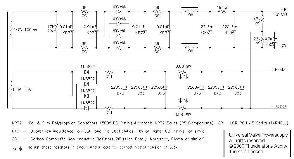
I believe one or two unusual features in this supply need explaining. First looking at the HT Supply there are a number of unusual networks around the very standard rectifier bridge. These are snagged from the late John “Buddha” Camille and have two purposes. The CRC pi-networks ahead and after the rectifier bridge help to reduce any noise. The use of carbon composite resistors in this position is mandatory to avoid resonance effects.
However, the chosen resistor values are unusually high, for a reason. They simulate the anode impedance of an EZ80 in full-wave mode. The resulting rectifier (with added networks) behaves very much like a valve rectifier, removing the often-notable unpleasant sharpness when solid state rectifiers are used. The diodes used should be soft recovery types but are relatively uncritical. Without having tested all available diodes I recommend the Telefunken BYV and BYW Series (I still personally use BYV96E as High Voltage rectifier of choice a decade later) as well as the Motorola MUR4XX Series. All these cost less and sound as good as the much-vaunted “HEXFREDs”.
Furthermore, the HT Supply circuit operates in choke input mode. For load currents of about 12 to 15mA the Maplin chokes can be used for choke input supplies. It is however necessary to place a piece of rubber between chassis and core to securely and strongly clamp the choke’s core in place as otherwise the core will buzz. I have myself used these chokes for up to 40mA choke input supplies in the described manner and fashion with no ill effects. Using one choke in each “leg” offers much improved common mode noise rejection and it doubles the inductance, compared to using a single one.
The rest of the circuit is bog standard, though the noise fanatics in the audience might want to replace the 1k filter resistor preceding the 220uF main filter capacitor with another Maplin choke. In my books the 1K filter resistor is just fine. Not shown here is the final filter stage that for each individual channel will be shown in the schematic for the analogue stage.
In any case these will be a 22uF Ansar Supersound polypropylene capacitor combined with a 4k7 Resistor. Ansar are now very difficult to source, recent production has also been reported as non too reliable, so SCR/Solen or Obbligato by www.diyhifisupply.com are now recommended, I note that the Obbligato Capacitors are generally thought of as sonically a bit better than Solen but have not compared them myself.
It should be noted that the above PSU Design is hardly ultimate or in any way maxed out. Significant improvements can be applied. However, the deciding criteria here were simplicity and reasonably low cost to get our project underway. More elaborate designs are open to anyone caring to implement them. Lastly, the very same supply is obviously suitable for any Circuit needing about 210V +B with 12mA (or less) current-draw and 6.3V Heaters with 0.6 to 0.7A current-draw. For the heaters up to about 1.2A can be accommodated if one of the 0.1 Ohm Resistors and one of the 0.68 Ohm resistors is bridged out. The HT can also support more current if resistors are reduced in value and capacitors increased.
5.2 Valve analogue circuits for multibit DACs
The circuits discussed in the following are suitable generally for any DAC chip having around +/- 1mA output current. This includes Analogue Devices AD1862 and AD1865 as well as Burr-Brown PCM56, PCM67, PCM69, PCM1700, PCM1702 and PCM1704. The Burr-Brown PCM63 and Philips TDA1541 will require somewhat different circuit values.
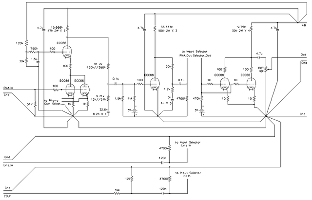
Due to a number of factors the circuit proposed is based around the SRPP circuit. This tends to be somewhat coloured sonically, however the specific colorations seem to blend well with digital audio’s failings, producing a generally subjectively pleasing sound in this context. In order to allow easy procurements of valves and reasonable gain as well as reasonably low output impedance the circuit is proposed for use with the ECC88/6922.
However, a 6CG7/6FQ7 can be used without changes. Even a 6SN7 can be employed if the higher heater current and the 8-Pin socket are accommodated. I know we have a few people in the circle who think the 6SN7 a good sounding and useful valve, even if I don’t. If desired the ECC83 or ECC82 can be used. In this case the cathode resistors should be increased to 3.3kOhm.
Depending upon Valve used the output voltage of the circuit will range from a nominal 2V RMS for digital full scale with the 6CG7, ECC82/12AU7 and 6SN7 in circuit, 3V RMS if the ECC88/6DJ8/6922 is employed and 8V RMS if the ECC83 is used. As a special case, the use of the 12AY7/6072A will result in about 3.5V RMS out.
The circuit includes a low pass filter and (I believe uniquely - at least I’m not aware of any other design that does) the de-emphasis correction. The low pass will produce a mild (0.7db) attenuation at 20 kHz, which should be innocuous. CDs using de-emphasis are rare, but they exist.
Many older CD players and DACs use analogue circuitry to carry out de-emphasis, so I believe the function must be provided where needed in the analogue stage. In this case R2 and C2 provide it together with the switch. The switch is ideally a high quality relay (mercury wetted reed relays are best) and needs to be controlled from the player’s/DAC’s internal logic.
The two parallel output capacitors are used to achieve a suitable load compatibility. The capacitors used are very high quality industrial Foil & Film types from Arcotronics or LCR and sold by respectively RS Components or Farnell in multiples of 5 and for a sane price. Their performance is broadly in line with Hoveland Musicaps. The resulting 0.94uF output coupling capacitance will allow loads of 20kOhm or higher to be driven without audible bass roll off.
While it is possible to further increase the capacitance, I would not recommend doing it in order to drive a lower load-impedance. For ECC88, 6FQ7 and 6SN7 the 20kOhm load possible in this configuration are the lower limit, for ECC82, ECC83 and 12AY7/6072 the load impedance should not fall below about 50kOhm and hence in this case even a single 0.47uF coupling capacitor will suffice.
All of this gives a basic circuit now almost a decade old (well, by now two decades - TEMPVS FVGIT) and well worn, but it still delivers the goods. Here is what it looks like:
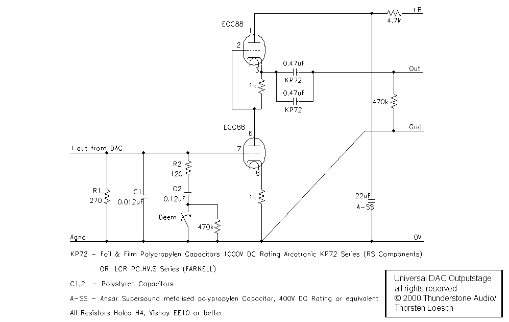
Now on to the PCM63 and TDA1541. The TDA 1541 is still one of the absolute best sounding DAC chips ever made (followed closely by the PCM63). Both chips are also fundamentally different from most other DACs of their kind by delivering 0 to (-) 4mA output current. In order to keep the error due to the non-zero impedance of the I/V conversion node limited it is essential to reduce the resistors in the circuit accordingly, that is to halve their values. Further we need to increase the capacitors to double their values. Yet we are still not there.
The PCM 63 is unique in that it allows us to disconnect the output from the pull-down current source. No such thing exists in the TDA1541. In order to offer a 0mA output at digital silence (that is NOT all bits set to zero by the way) almost all Multibit DACs use a pull-down current source offering a - ½ full scale current offset, zeroing the output at digital silence.
The PCM63 allows us to eliminate this current-source (a bunch of transistors, resistors and Jah knows what else), simply by disconnecting pin 5 (offset) form pin 6 (output). Having done that we are left with a DAC that will swing now from (-)2mA for digital silence to 0 and (-)4mA peaks for negative or positive full-scale signals, respectively.
It is in this mode that the highest degree of sound quality from the PCM63 is realised, at the penalty of a ½ full-scale offset. In many circuits the measures required to eliminate this offset would be worse than the problem, so this is rarely done. In our own little circuits the offset matters little and hence we can safely employ this scheme. The highest value of I/V conversion resistor usable before significant distortion becomes notable is 100 Ohm in this case for the PCM63. Similar Limitations apply to the TDA1541
We hence need to substitute the following values:
- R1 = 100 Ω
- R2 = 43 Ω (44 Ω accurately)
- C1 = 33 nF
- C2 = 330 nF (320 nF accurately)
By the way, I’m looking at making a DAC using the PCM63 kindly donated by Geoff Mead which will use the above with a Euridice style amplification stage and NO digital filter.
The circuit wise similar Audio-Note UK made dac5 (at a whopping £18,500 retail) was just (well, just a decade ago, when the British Pound was actually worth something!) noted by Martin Colloms in HiFi-News as “best from CD so far” and uses actually a much inferior chip, the AD1865 a dual 18-bit Multibit DAC. Martin noted a subjective quality approaching that of experimental new high-resolution digital systems (96kHz/24bit and SACD). Perhaps it’s time to go out and buy the last remaining PCM63 and TDA1541 before they walk in order to make THE DEFINITIVE CD format DAC.
With a decade passed SACD has come and is nearly gone (and is having a second coming as downloadable files) and DVD-Audio may not be dead, but it certainly smells rather funny. The bloody, gory format war between SACD and DVD-Audio Disks that I satirised in 1998 was a non-event; no-body cared enough about the new media to make the fight worth fighting. High resolution audio, that is Audio exceeding the CD sample rates and word length is finally becoming more common as downloads, however they only play via computers and similar devices, not traditional disk players, so CD has remained the dominant music format, with LP making a small but surprising comeback.
And with all this time past, I still find the combination of TDA1541 and valves to be the most analogue sounding and satisfying way to reproduce CD-Audio and I still find that such a combination implemented well offers a sound quality that at least closely approaches that of the better SACD Players playing SACD and that of well (if not exceptionally) implemented DVD-Audio (read 24/192).
5.3 Valve analogue circuits for time-slicing DACs
As noted before, the time slicing or delta sigma DAC doesn’t really need any analogue stage in order to provide enough voltage output. However, due to its ill conceived modus operandi we require low pass filtering and (if we insist on being boring and conservative) a balanced to SE converter in case of most high performance devices.
Let’s first split the range of time slicing DACs into three groups. The latest, most recently introduced group uses extensive on-chip analogue stages, sounds by far worst of the lot and for some reason receives in its implementations consistently rave reviews*. These are as mentioned the Burr-Brown PCM1710/16/28/32, Philips TDA1305, Cirrus Logic CS4327 and Analogue Devices (insert list).
*Either reviewers are blinded (or deafened) by the “24-Bit” claims for those chips or the fact that finally the last bit of control over analogue performance has been taken away from the CD player Designer stops them from screwing up the sound of potentially better sounding devices up. Whichever way, I’m just not getting it.
I suggest taking the hint from the manufacturer. Just take the output pin of the DAC chip directly to the output jack with only a good quality coupling capacitor in-between. Believe me, it truly does sound best. The on-chip filtering is usually sufficiently good to not cause any problems even with solid state equipment. A valve buffer (cathode follower) can be employed, just as per the circuit below, but again, I do not feel, that it improves anything.
I must also note that I personally find the sound coming from these new devices to be exceedingly poor, when compared to really competently implemented multibit DACs or earlier generation timeslicing DACs. (Well, the trend has been reversed somewhat, current budget DACs are quite a bit better than their forerunners a decade ago, yet the best chips are still old multibit or differential output hybrid designs.)
The generation before the latest designs is a bit more heterogeneous. We find many DACs with differential output but various different schemes of on chip filtering and buffering and the occasional DAC with single-ended output and really good on chip analogue silicon. In the latter case (CS4328, certain OEM Products) the same as above holds true. For all other differential output DACs the circuit shown further down should/could be used and should work under any conditions, offering good filtering and ensuring an easy load for the DAC chip, keeping distortion low.
Finally, the original first-generation timeslicing DACs have no analogue stages; some of these are early Philips chips as used in the QED “Digit” external DAC, also the NPC SM5872 (Marantz CD-53/57/63/67 among others) and NPC SM5864 (Arcam Alpha - lower models) and surprisingly many OEM chips even in current use. All these will require some buffering and due to the lack of on chip filtering a direct connection without any additional low pass filtering even to high impedance inputs is not advisable. Again, the circuit shown below will work just fine.
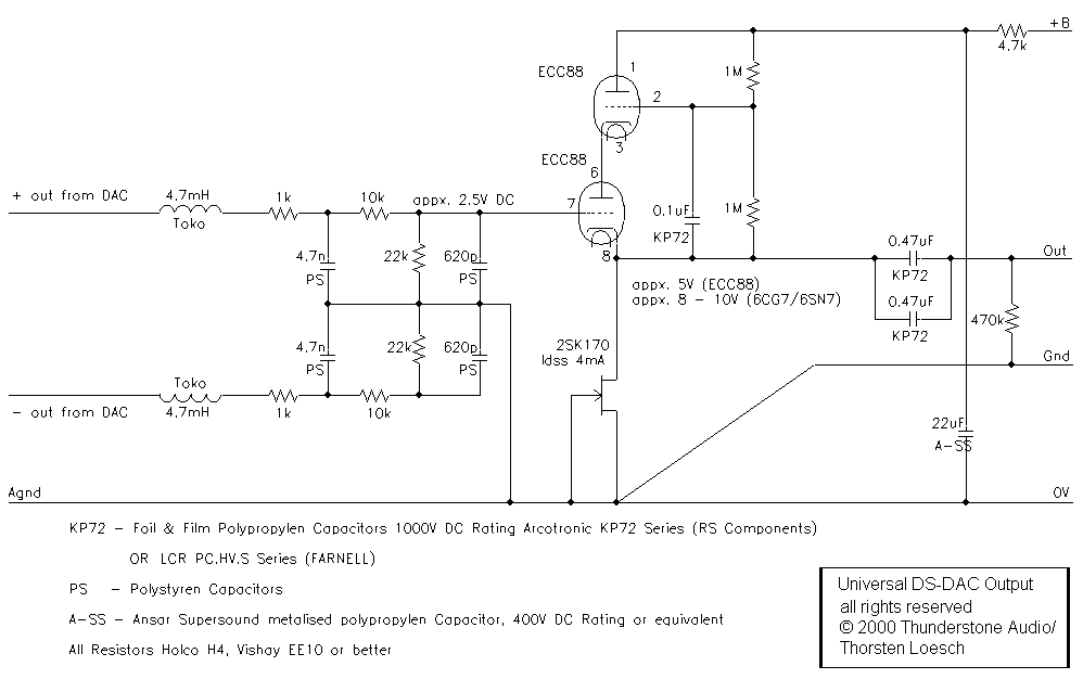
The circuit seems very novel, but it is not at all so. The differential filter at the input of the circuit is used in order to present an identical load to either output of the DAC and to implement a well-damped 3 rd order low pass filter. Again a small loss (about 0.8db) is allowed at 20 kHz. The positive output of this filter is then buffered by an ECC88 cathode follower.
This cathode follower has been subjected to some improvements over the classic version. By bootstrapping (or cascoding) the anode of the follower valve the circuit is linearised. The use of a J-Fet connected as current source in the cathode of the follower valve serves the same purpose. More on this circuit can be found in Allen Wright’s “Valve Preamp Cook Book” and hence it will be not discussed much further.
The usual 2.5V DC offset on the DAC Output is put to good use in order to provide additional bias to the Grid of the follower valve. This allows about 4 to 5V to develop on the cathode, more than enough voltage headroom to allow the about 1V RMS output to be buffered with low measured (and perceived) distortion.
It is possible to use a simple “classic” cathode follower in the above circuit. This will certainly result in a much more “valvey” and possibly subjectively preferable sound. In this case the ECC82, 6CG7/6FQ7 or 6SN7 seem ideally suited with a 2.2kOhm resistor in the cathode. An ECC83 might be employed with a 3.3kOhm cathode resistor.
The sound will be very different to the circuit shown above. Mostly transparency will be substantially compromised, however the subjective result might be considered pleasing. Perhaps it is worthwhile trying designs, the classic and the “Super Linear Cathode Follower”.
In 1999 I was rather prejudiced against using local loop feedback around a single valve stage. Hence, at the time I did not include this option. I have since had ample time to work with this circuit and to cure myself of this prejudice. By all indications the circuit above has been build many times and has its followers; however I do not use it or its like any more. The following circuit is the one that should have perhaps been included in the original article at the time, instead of what was published above.
It is designed to operate direct coupled to DACs with a voltage output and with 2.5V DC offset. The circuit contains a first order RC input filter that is differential, just as with the 1999 circuit. Unlike the 1999 circuit it only uses a first order filter. This is because the following active circuit offers another inherent low pass, so in combination a second order low pass with a -3db point of 60KHz is generated.
This 60KHz filter is sufficient for modern hybrid DACs, which have in essence replaced the pure time slicing / bit-stream designs by now even in very low cost designs. For those modifying CD players or DACs using very early bit-stream DACs the original LC/RC filter can be used and applied instead in a “cut and paste” fashion.
This first order lowpass is followed by a circuit that combines the SRPP circuit applicable to the multibit DACs with the local feedback loop taken from the so-called “anode follower” circuit. The combination gives the correct gain for voltage output DACs to produce 2V RMS output and provides low output impedance.
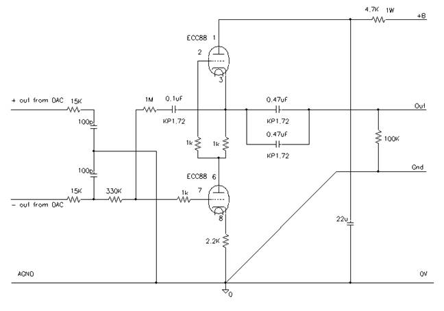
Sonically I feel that this design is somewhat more interesting and alive sounding than the super linear cathode follower presented in 1999. It can work well with all the differential and single ended output DACs that have their output overlaid with around 2.5V DC and produce 1V RMS output at full scale, which includes practically any current design that is not covered by the multibit design.
Thus slight variations of the same basic design are applicable to nearly all DACs under this sun, so one may change the DAC chip dramatically but keep the valve circuit mostly unchanged.
5.4 The DIYHiFiSupply Universal Valve Stage
Over a year ago Brian Cherry from www.diyhifisupply.com asked for a simple and compact valve analogue stage for a DAC he sells. The design I eventually came up with drew heavily on the designs presented in this article.
It was decided to make the circuit universal enough so that it could work both as straightforward gain stage for current output multibit DACs and as anode follower with a gain of 2 or 4 for voltage output DACs (and fill many other roles in line preamplifiers, phono stages and pro audio designs).
Using a few jumpers just as on old computer motherboards allows the Universal Valve Stage board to be configured to work with pretty much any DAC under the sun with (re)configuration taking a few 10 seconds.
For people more hardcore who dislike jumpers, it is of course possible to “solder-bridge” across the jumpers, though to be honest the gold plated brass jumpers do not seem to affect the sound quality that unduly.
Unlike the earlier designs I cannot present a full design circuit of the Universal Valve Stage, as it is a commercial design paid for and owned by www.diyhifisupply.com. What I can present is the principle schematic also included in the manual and a picture of the whole thing.
The gain stage is a hybrid Mu-Follower using a self-adjusting current source as load for the ECC88/6DJ8/6922 Valve. Jumpers are used to select different values of current/voltage conversion resistors as well different configurations of the anode follower configurations.
The power supply is derived from the “simple” design, however it substitutes the large and heavy chokes with an electronic version called a zener follower and integrates the resistance for the snubber into the custom transformer. This circuit is a zero feedback supply design also found for example in the top of range Conrad Johnson preamplifiers.
The UTS is also fitted with a mute circuit that can be triggered by the DAC’s or CD player’s circuitry and offers a turn-on delay to remove switch-on and switch off thumbs.
Fitted with screw terminals (which can be removed to allow direct soldered connections instead for those sufficiently possessed of audiophilia nervosa to care about that kind of stuff), the whole makes a very compact and quite easy to installed module. It can fit easily inside most digital players and DACs with a size of 140mm X 80mm X 45mm size. It normally comes with the matching low noise torrid mains transformer pictured.
If you get my favourite NOS Tesla ECC88 Valves and tinfoil & polypropylene output coupling capacitors included, the total comes to 230 US Dollar plus shipping, which while not exactly beer money or small change is about the same money the original Musical Fidelity X-10D “missing link” sold for in 1999.
However, unlike the “missing link” it is not a band aid to be applied after a conventional CD player but a fundamental replacement for the solid state analogue stage in any kind of digital sound producing device, from CD and DVD Players through DACs to satellite radio receivers, I suspect it can even be used in PC cases to upgrade the analogue stages of computer soundcards.
As a final teaser, here a picture of a Marantz CD-80 that was converted from the standard op-amp output stage to the UTS, had the digital filter bypassed and also had the EZ Ultimate Clock system fitted.
Conclusion
Armed with the designs shown above (and especially the Universal Valve Stage) as well as the background information presented it should be possible to convert any available digital audio replay device to a state with a more transparent, less subjectively compromised design. Most CD players and DACs will have sufficient internal space to fit both the valve circuit and the PSU parts.
The perhaps best mechanical solution for most CD players would be to obtain a suitable sized aluminium box/chassis from Maplin (the 150mm X 114mm X 76mm one looks right). This would be attached at the rear of the Player or DAC and one would run some flying leads from the Player/DAC circuitry trough some holes in the rear panel (how about the ones previously containing the output jacks) into the valve stage.
All other components and the PSU could be placed safely in this separate chassis and again, the mains power could be send through another suitably drilled hole, making the whole solution neat, tidy and professional looking. If done well enough it would even allow the Player/DAC to be returned to stock condition with no major cosmetic blemishes.
Now I suspect that some people would think it having been convenient had I listed in detail the relevant Pin’s on all noted DAC chips and provided more practical notes on the way these are accessed. This was not done for a number of reasons. Primarily I feel that anyone should get a service manual for their piece of equipment before starting to work on it. This will contain a schematic that has the relevant information on it.
If such a schematic, even if present would not be able to convey the needed information, perhaps it would be useful to take someone reasonably experienced with digital audio circuits and their modification as “mentor” for the specific project. And kindly find some-one else than me.
If you need support to implement the www.diyhifisupply.com Universal Valve Stage please e-mail diyhifisupply directly, some of the money you pay for their products goes towards bailing you out when trouble arises.
Till the next piece, have fun and Enjoy The Music.
About the author
The 2010 edition carried an author biography here. It is superseded by Who the Fudge Am I?.