
Design
This Is the Lux91, a Western Electric 91 with a Reactive Interstage
300B single-ended monoblocks designed for DIY HiFi Supply in Hong Kong: the WE 91 gain stage, a reactive interstage, fixed bias and a film-capacitor supply, 16 W from one 300B. By Thorsten Loesch.
Original title: The Lux91 MonoMax
Lux91300BTube Amp Theory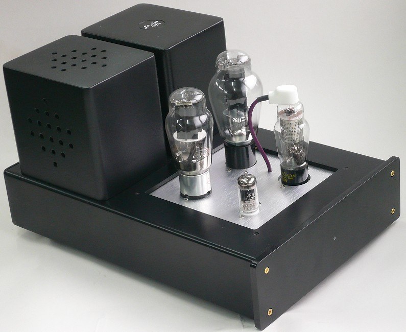
In many ways the Lux91 is where all the concepts discussed in my article Some Thoughts about Single-Ended Valve Amplifiers come together, and it is their high point:
- Direct-coupled cathode follower drive gives real improvements in both power output and overload recovery.
- A single pentode gain stage gives an optimum harmonic profile.
- A stiff, regulated power supply keeps rail impedance to a minimum.
In the terms of my position paper The Audio Heretick’s Progress, it is an illusion engine designed for audible fidelity, not for a set of FOM: figure of merit. A single number, such as THD+N, SINAD or jitter in picoseconds, used to sum up signal fidelity, with the claim that a better number means better sound. It relates to audible fidelity only at the extremes. The Audio Heretick's Progress: the FOM →.
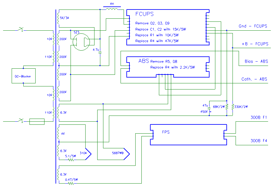
The specific “technology modules” and the mechanical and transformer platform are long gone, but the principles behind the design remain fully valid. The design files I kept, or was able to recover after DIY HiFi Supply, are available for download: the original 2010 manual, the Active Bias System and the DHT heater supply schematics and PCB layouts, and the Film Capacitor Universal Power Supply manual.
For a 2026 refresh of this design, as an example, the 5687WB cathode follower could be replaced by a MOSFET such as ST’s STD4N90K5 (900 V, 3 A, very low capacitance), and a 6SN7 cascode could be used instead of the 310A pentode.
The Lux91 MonoMax was sold by DIY HiFi Supply in Hong Kong from 2010, as a kit and assembled. The circuit, the manual and the technical writing about it were mine, including what appeared under the company’s name. This article is put together from my 2010 manual, my answers for the 6moons review and my forum posts about the amplifier.
How it started
The original Lux was a custom design for one particular reviewer, who used speakers of around 93 dB/W/m. He had tried another of my custom amplifiers (a choke-loaded D3a driver and a 300B at 350 V/60 mA into 5k) and liked its sound much better than a very expensive 300B parallel single-ended amplifier, but at around 7 W it did not give him enough power. So the first Lux was born, and then people asked to buy the same amplifier…
That first Lux (late 2007) used an EF86 gain stage and made 12.5 W. The Lux91 MonoMax is its development: the gain stage of the Western Electric 91 with a 310A, the reactive interstage from the Lux, fixed bias, and a power supply built for headroom, in a pair of monoblock chassis.
Why the WE 91?
When Joe Roberts published “The 300B Amplifier: A Model 91 for 1992” in Sound Practices in the summer of 1992, the 91 was already nearly 60 years old, and since the late 1970s it had been rediscovered by enthusiasts in Japan, Germany and France. Just as Helen of Troy has been called the face that launched a thousand ships, that article could be said to have launched thousands of enthusiasts onto the seas of single-ended amplifiers, and quite a few boutique makers with them. It was the compelling, musical and realistic presentation of this amplifier that reopened the market to low-powered single-ended amplifiers.
The original 91 had many limitations, dictated by the 1930s idea of high fidelity for cinema sound. Neither the bass nor the treble extension is great; the magic was strictly in the midrange. The treble limit is hard to overcome, while low bass is easy to add, but then the amplifier no longer sounds balanced.
The 91 also lacks power. Its driver stage has a very high impedance. Where a low-impedance triode driver can get over 12 W out of a 300B at the 91’s operating point, the 91 brings a measly 7 W to the table. And when it overloads, it does not show the gentle compression of many triode-driven designs, it clips in a hard straight line, just like a transistor amplifier. The WE 91 is a gentleman’s amplifier: its forte was never the extremes, but the middle, civilised small-scale music rather than large and noisy pieces.
Many designers have since piled complexity upon complexity on something as simple as a 300B SET. Such amplifiers may beat the proverbial crap out of the WE 91 on bass, treble and power, yet at their core they often lack its natural, immediate and delicate sound. The question was how to keep the 91 and add what it lacks: power, dynamic range and graceful overload.
Three ways to drive a directly heated triode
- A pentode. It gives the necessary gain in one stage, but its output impedance is high, so treble and bass tend to be limited, and it clips nastily. The sound is delicate, immediate and fast, with a “bouquet of tone”, and it finds the finest details. It can swing the voltage, but do not ask it to lift heavy objects: the directly heated triode needs more muscle.
- A triode. It lacks gain, so it needs more than one stage (and high-gain triodes sound like solid state). Low output impedance, wide bandwidth, great slam and dynamics, and with a grid choke even more perceived power. Muscular, but it lacks the refinement and delicacy of the best pentodes and leaves some of the fine detail behind.
- The reactive interstage. A pentode at the input, then the paralleled sections of a triode with a choke in the cathode, direct-coupled to the grid of the output triode. The pentode does what it does best, giving lots of voltage gain into the undemanding load of the interstage. The output triode gets what it likes: lots of voltage swing and iron-fisted control, even when its grid is driven positive.
The result is the tone and refinement of a pentode, married to the slam and dynamics of a triode.
The reactive interstage
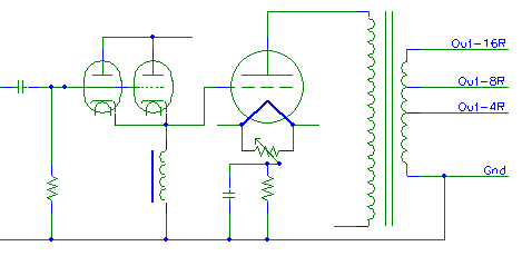
The “eureka” moment was to make a special grid choke for the output valve also serve as the cathode load of the driver valve. The driver’s cathode is then loaded only by the choke and the output valve’s grid, a very high impedance for music signals, so the driver is not stressed. Of course not just any choke will do: careful design is needed to balance all the conflicting parameters. The output valve still sees a low DC resistance to ground, but, more importantly, it is also driven from a very low impedance for music signals. The circuit has a relative in the cathode-follower-and-choke stage of the 1950s Altec 1570 push-pull amplifier, but here it is optimised for a single-ended 300B.
As the output valve’s grid comes close to the cathode voltage, it starts to draw more and more current. The 5687 reactive interstage can supply short-term peak drive currents of as much as 70 mA, so the driver handles much more input without collapsing. The choke releases energy on signal peaks, which a resistor cannot do. With no coupling capacitor to the output valve, nothing charges up on peaks and shifts the bias afterwards; the original bandwidth limit is gone, too. The interstage is loaded only by the following grid and the cathode choke, so its bandwidth reaches from DC to light, and the output valve sees the choke as its very own grid choke.
The overload behaviour changes completely. With typical valve amplifiers, as power approaches maximum, the output valve’s grid starts drawing current. With a high-impedance driver, as in the WE 91, the amplifier clips hard before ever reaching full power. With a low-impedance triode driver, the driver supplies the grid current up to a point, but that current charges the coupling capacitor, which again reduces the current in the output valve, so the amplifier overloads before reaching full power. Worse, these power-limiting effects have a time constant: they last for a while after the musical peak has passed, so we hear the amplifier change its sound as the music moves towards and past a crescendo. Combining capacitor coupling and self bias invariably brings these problems. Such amplifiers may sound very good at low levels or with simple music, but pushing them quickly reveals their limits.
With the reactive interstage, clipping no longer happens in the input or driver stage, with its hard, solid-state-like unpleasantness. Only the output stage clips, and triodes do not clip hard. They show a soft clipping and compression characteristic that needs a lot of overload to become subjectively annoying, and a small amount is easily tolerated.
The complete circuit
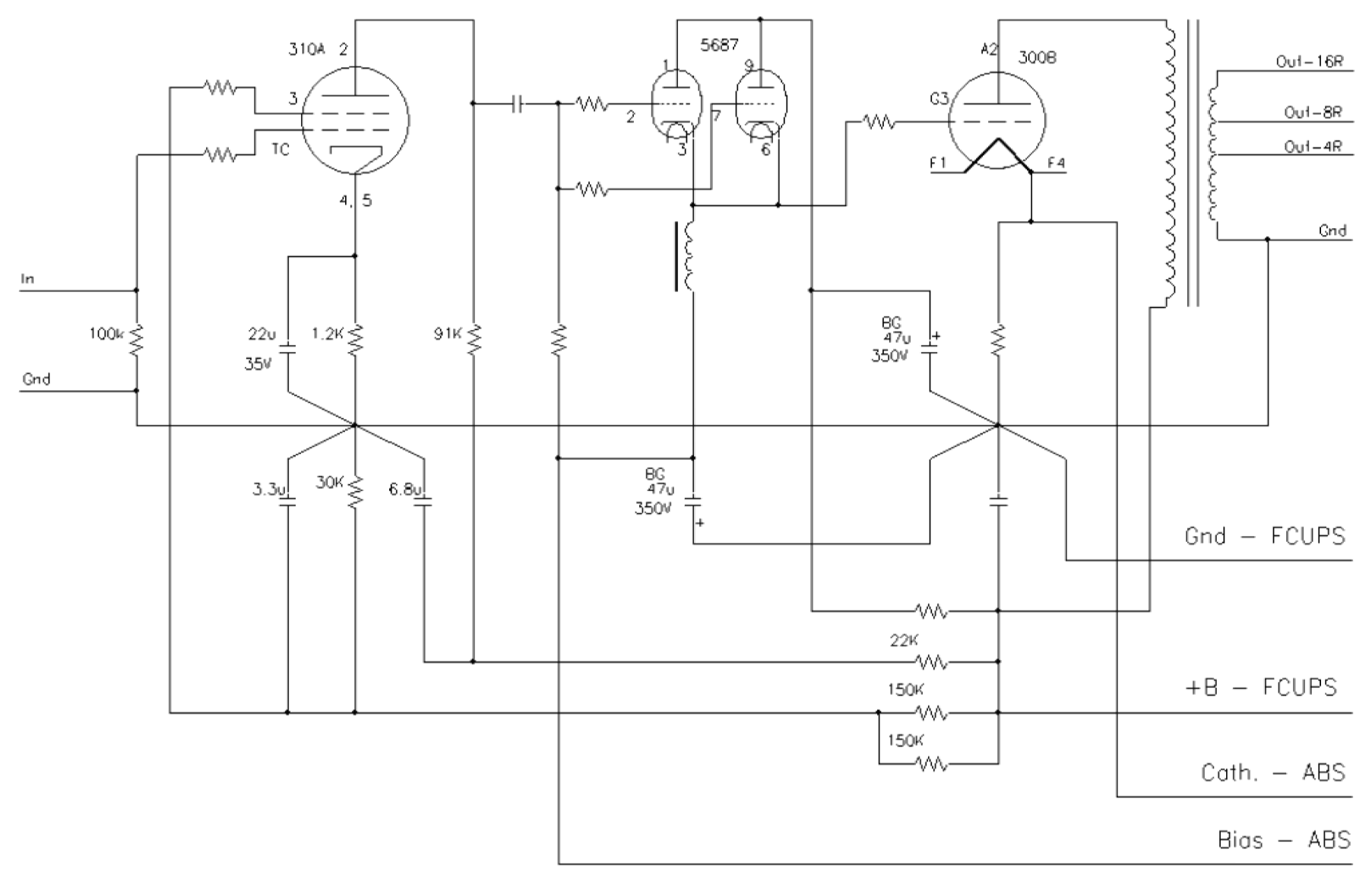
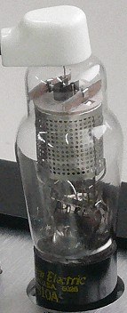
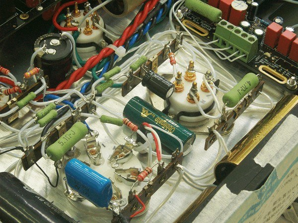
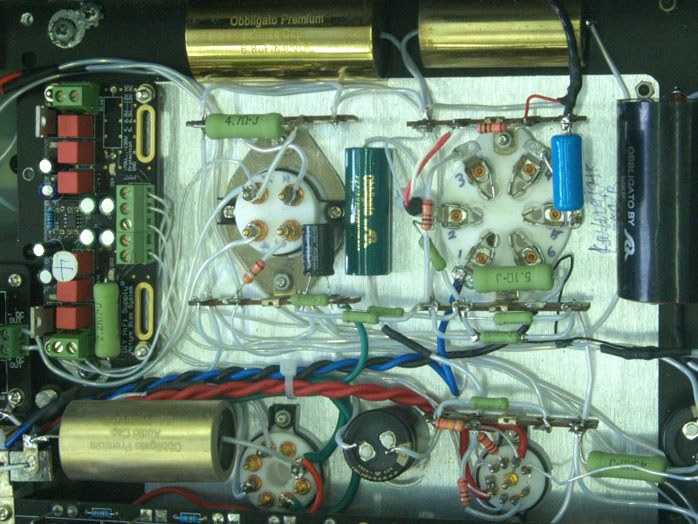
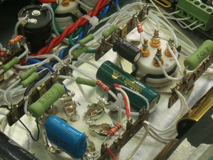
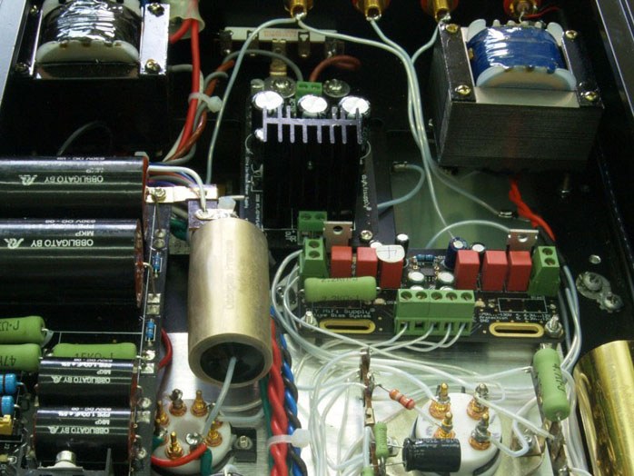
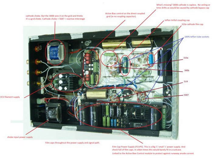
The gain stage is exactly the circuit of the mid-1930s Western Electric 91, with the 310A pentode in its characteristic coke-bottle shape and top grid cap. Obbligato film capacitors decouple the supply and Japanese Kiwame resistors sit in the signal positions. In keeping with the original, even the 310A’s cathode capacitor is not an electrolytic but a special 22 µF/35 V film capacitor. All connections are hard-wired in solid-core silver wire, sleeved in Teflon. The only coupling capacitor in the whole amplifier is a 0.22 µF Teflon and tin-foil type, chosen for its unmatched sound.
It is followed by the heart of the circuit, the choke-loaded 5687 reactive interstage, with a Black Gate capacitor in its supply, direct-coupled to the 300B. The output transformer was wound by Silk Transformers in Thailand, with specially heat-treated 0.014 in cold-rolled grain-oriented silicon steel laminations and winding techniques for the widest bandwidth.
So from the input RCA socket the signal passes through Teflon-insulated silver-plated copper wire, the 310A, one PTFE and tin-foil coupling capacitor, the 5687 follower, the 300B and the output transformer, with quite a bit of silver wire in between.
Sixteen watts from one 300B
The relatively high power was not really the main design goal; it is more a side effect of the other goals. Western Electric’s own 300B data sheet shows a wide range of operating conditions, with class A1 power up to 17.8 W. The original WE 91 ran the 300B very conservatively, because those amplifiers were leased, not sold, to cinemas, and WE remained responsible for their upkeep.
The Lux91 runs the 300B at 400 V/80 mA, 32 W anode dissipation instead of 28 W at 350 V. That is still conservative, well inside WE’s maximum ratings of 450 V/100 mA/40 W. With the gains from fixed bias, it delivers 16 W (at 10 % THD) from a single 300B, against the 8 to 9 W of more conventional designs.
With cathode bias, maximum power is restricted, because the circuit reduces the output valve’s current as power rises. Classic cathode bias also puts a resistor and a large capacitor into the output valve’s signal circuit, and the quality of both critically affects the sound. Fixed bias removes both, but has its own reputation: bias that needs frequent readjustment, current runaway and valves eaten up. The Active Bias System module gives the benefits of fixed bias with the ease of use and reliability of cathode bias, and keeps the operating point nailed down as valves age or different ones are tried. On the 300B cathode there is only a single small, very high-quality resistor, and no capacitor.
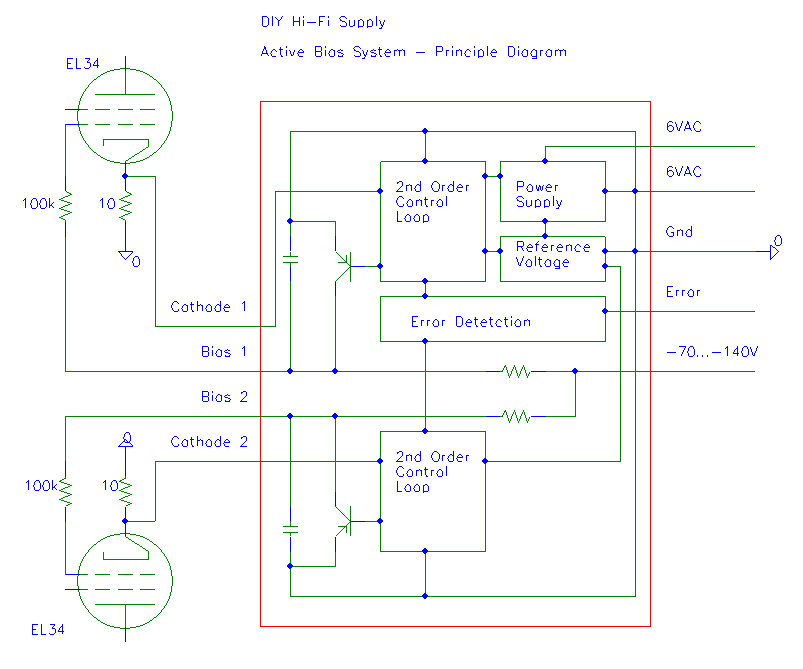
How it works: for each output valve, a small resistor in the cathode senses the valve’s current. A second-order control loop compares it with a reference voltage and sets the grid bias through the grid resistor, slowly enough not to touch the music. An error detector flags a valve that can no longer be held at its operating point.
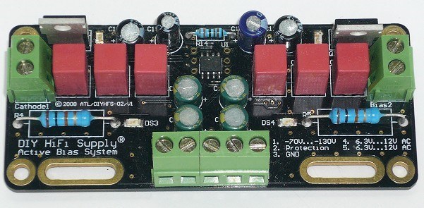
The module itself runs from a 6.3 to 12 V AC winding and the negative bias supply (−70 to −130 V). Each channel has its own control loop, half of a TL082 op-amp, with a TL431 as the reference; a high-voltage A940 transistor sets each valve’s grid voltage, and LEDs show the protection state.
The full schematic and PCB layout, from my 2008 design files, are in one PDF: Active Bias System (PDF).
The power supply
The supply is choke-input, with a 5U4 rectifier, then a further low-resistance choke, then the Film Capacitor Universal Power Supply (FCUPS). The FCUPS was developed as an active alternative to very large chokes and capacitors: it behaves like a massive 500 H filter choke with very low resistance and nearly 1000 µF of film capacitance, without the size, weight and cost. It also brings the output valve up to its operating point slowly and gently. There are no electrolytic capacitors in the high-voltage supply, only film.
How the FCUPS works, briefly: a sample-and-hold circuit tracks the lowest point of the incoming ripple waveform and stores this voltage in a capacitor. That voltage is the reference for the gate of a MOSFET. Because the MOSFET’s gate threshold voltage is around 3 to 4 V, the supply always stays “in regulation”.
In the terms of my single-ended amplifier article, it is a zero loop feedback series regulator with very low output impedance. Yet it behaves more like a choke and capacitor filter supply: it drops only a minimum of voltage, and it tracks changes in the mains voltage.
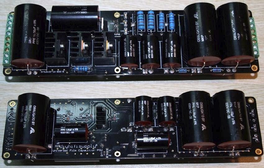
How it works: the “electronic choke”, two IRF830 MOSFETs in series, follows the lowest point of the rectified and first-filtered supply and drops only about 6 V more, so it tracks the mains like a choke-input supply. A jumper selects “virtual battery” mode, where the output behaves like a very large choke and capacitor followed by 10 Ohm and 20 µF, or “virtual choke” mode, for use with a large external capacitor. The module also makes the negative supply for the bias, −80 or −140 V by jumper, and takes the fault line from the Active Bias System, which shuts the high voltage down if an output valve cannot be biased.
The full installation manual, with input and output wiring for solid-state and valve rectifiers, bias options and example circuits (2A3 and 300B single-ended amplifiers and a balanced line stage), copyedited, with the schematic: Universal Film Capacitor Power Supply manual (PDF).
The 300B filament runs from a filament supply module with very low noise that acts as a current source for music signals: a very high impedance at audio frequencies, like a choke used as a noise filter, but with the fit-and-forget stability of a voltage supply. It ramps the filament voltage up gently, reducing inrush current and stress on the output valve.
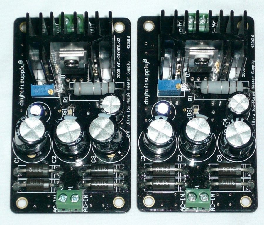
The schematic and PCB layout of the filament supply, my Low Noise DHT Heater Supply V2 from 2008, are in one PDF: DHT Heater Supply (PDF).
All these headroom measures, the choke in the interstage, the stiff supply and the fixed bias, only come into play when needed. They do not change the sound of the WE 91 at lower levels, and they do not stress the output valve unless it is asked for short musical peaks with authority. DIY HiFi Supply called this P:USH, “Power for Ultimate Signal Headroom”. In summa thermionica: an amplifier that goes to 11, where common amplifiers using the same valve often do not even reach 10.
Specifications
| Output power | 16 W at 1 kHz (10 % THD), class A, from one 300B |
| Frequency response | 12 Hz to 47 kHz (−3 dB at 5 W); 20 Hz to 20 kHz (−0.5 dB) |
| Distortion | below 1 % THD at 5 W, 1 kHz |
| Signal-to-noise ratio | 100 dBA or better (0.4 mV at the speaker outputs) |
| Input | 1 V, 100 kOhm |
| Outputs | 0, 4, 8 Ohm or 0, 8, 16 Ohm |
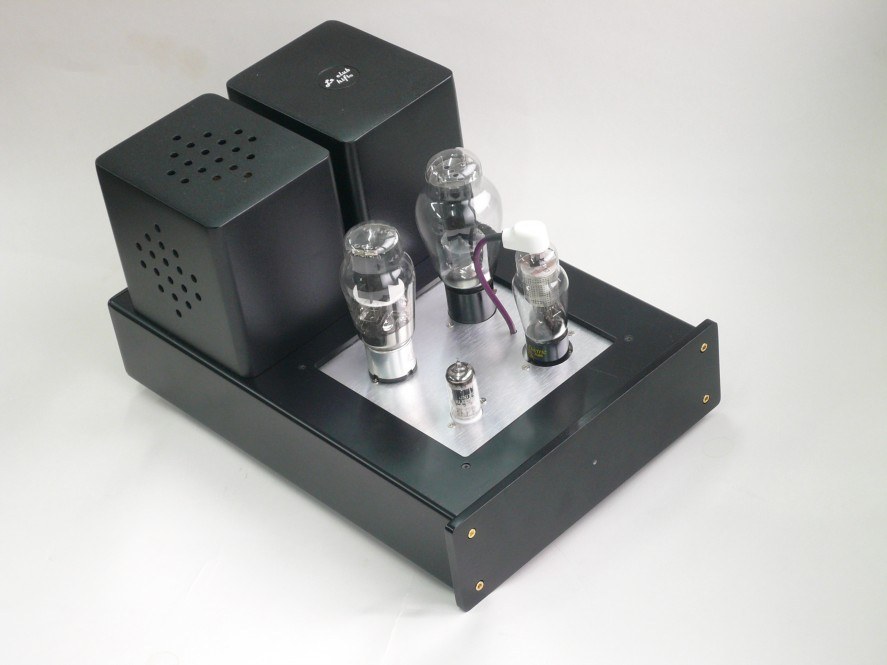
| Valves per channel | 300B, 310A, 5687, 5U4 (or 5Z3P, 274B) |
| 300B operating point | 400 V/80 mA, fixed bias |
| Size | 370 × 240 × 210 mm per chassis |
| Weight | 13.5 kg per chassis |
Speakers and output taps
With all that headroom, the Lux91 can drive speakers at the lower end of the “high efficiency” scale. Many more good speakers exist at a real 93 to 94 dB/W/m than at 97 to 98 dB/W/m, and in many cases even around 90 to 91 dB/W/m works. Just do not book a first-row, live-concert experience of Mahler’s Symphony of a Thousand, and do not use it with notoriously power-hungry loads such as Dynaudio mini monitors or a BBC LS3/5.
Which output tap is right? Think of the output transformer as the gearbox in a car. The engine likes high revolutions and fairly low torque, just as the valve wants high voltage and low current. The road wheels want low revolutions and high torque, just as the speakers want low voltage and high current. In the car the gearbox translates one into the other without much loss; in the valve amplifier the transformer does. With the wrong gear you either cannot get going or cannot reach speed even with the accelerator floored. With the wrong output tap the result may not be what you want either, and which is right is hard to predict from the specifications. The tap that “sounds right” usually also gives the better match between speaker and valve. Valve wear, by the way, depends on cathode current and dissipation, not on the tap; and the Lux91 soft-starts both filament and high voltage very gently.
Questions people asked
Can it be made for the 2A3? No, nor would there be much point. The Lux91 is explicitly designed as a “max headroom” and “max power” amplifier, so it needs 300Bs, and ones that are no frightened mimosas either. I also doubt this kind of circuit would harmonise with the “sound of the 2A3”, if there is such a thing. For a 2A3, the Lady Day or Lady Day 91 would be the better choice.
Emission Labs valves? They have thicker pins, and in the high-grade PTFE sockets they expand the contacts, so other valves no longer make good contact afterwards. Used only with EML valves they work fine, but you may have to change the sockets if you ever go back.
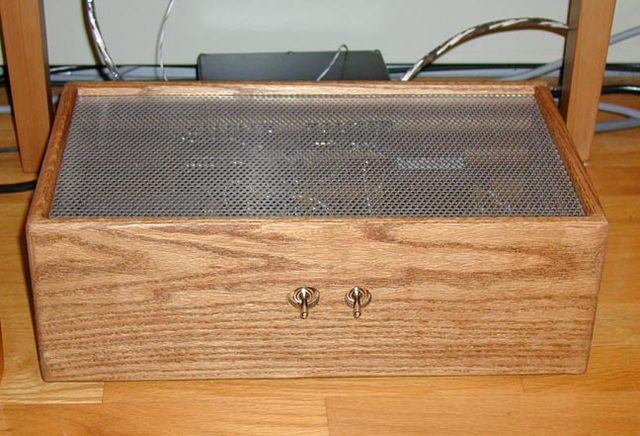
Why is the power switch at the front? That is my fault: I find rear switches a major pain, so I had it changed. The mains wiring runs on the opposite side of the chassis and is twisted, so there is nothing to worry about.
How far can the 91 be taken? For now, most likely to the limit of what may still, with some justification, be called a 91 and actually sounds like one. Anything that improves significantly on it would have to be redone from the ground up, probably with different output, driver and gain valves. But that would not be a 91 by any stretch of the imagination: a whole nother story, and amplifier.
Further reading
The Lux91 MonoMax was reviewed by Chris Redmond for 6moons in May 2010: DIY HiFi Supply Lux 91 Max monos. The amplifier was also discussed on diyAudio in the thread Lux91 Monoblocks - Our Best Ever.