
Design
This Is How a 300B Kit Became a Two-Stage 437A Amplifier
A Chinese 300B kit rebuilt with a single high-gain triode driver, chokes where it counts and a quiet supply, by Thorsten Loesch. Translated from the German original.
Original title: A 300B Single-Ended Amplifier with a WE 437A Driver
437A - 300B300BTube Amp Theory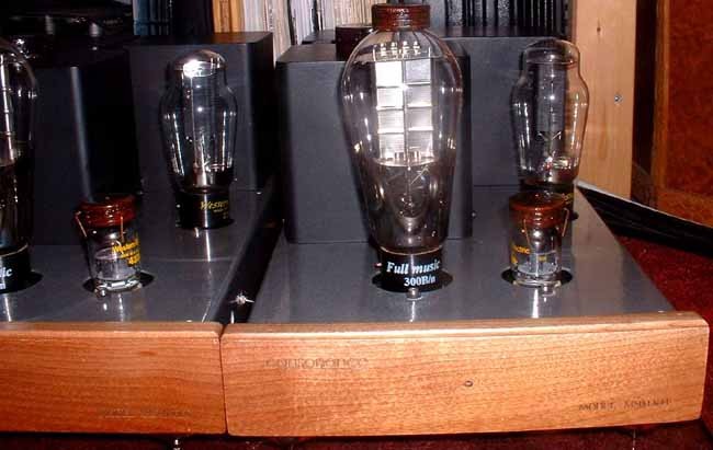
This amplifier started as a modification of the “Billie” kit from China (diyhifisupply.com). Apart from the case and the main iron, practically nothing was kept. The original kit is a perfectly decent cookbook 300B single-ended amplifier: a 6SL7 SRPP driver stage, a cathode-biased 300B at 400 V/80 mA, valve-rectified high voltage with CLC filtering, and the usual bridge rectifier plus 10,000 µF electrolytic for the heater supply.
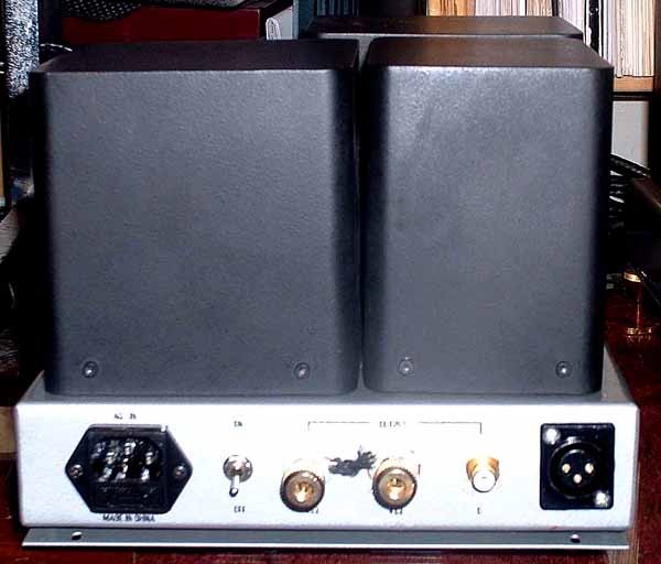
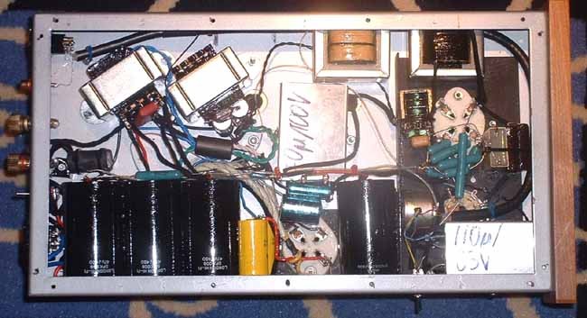
The modified version grew step by step, through several more or less complete rebuilds. The wiring could be tidier, but repeated rebuilds and relocated parts left some leads routed less than ideally. I will spare you the history of the intermediate versions and describe only the “final” circuit and parts. Many details were chosen by comparative listening; some of those tests were done with this amplifier in its earlier forms, others elsewhere.
Parts
The parts may look exotic and “high-end”, but note that ABSOLUTELY none of the boutique parts with astronomical prices so beloved in high-end circles were used. The great majority are either high-grade industrial or military parts (including some made to order) or old military surplus. The valves, apart from the output valves (I have a veritable collection of modern 300B copies from China, Russia, the USA and the Czech Republic), are Western Electric, in this case new-old-stock from American telecom service workshops. Electrolytic capacitors were avoided wherever possible: their poor long-term stability, clearly measurable distortion and often extreme microphony more or less rule them out for high-quality amplifiers.
The wiring is 0.07 mm pure silver wire, bare, in oversized cotton sleeving or oversized polyethylene tubing. Teflon is best avoided with silver. The silver surface is exposed to the air and so oxidises, but to my ears this is preferable to every coating I have evaluated. The same cannot be said for copper.
All resistors are vitreous-enamel, non-inductive wirewounds made by Painton in England. They have pure silver leads (I did not believe it either, and had them analysed), and the resistance wire is welded directly to the leads. They are military surplus. Similar modern resistors are made by Rohpoint, Elisabethhütte and others for low power ratings; for high power, Mills is the choice. None of the alternatives has silver leads, though.
The circuit
A two-stage design appealed to me because it leads to a much “cleaner” distortion spectrum. The common solution, the two halves of a 6SN7 (or an E182CC/5687) in cascade, produces excessive higher-order harmonics and a rather uneven overall harmonic spectrum. Driver circuits with a single valve are much cleaner by comparison.
The 6SL7 SRPP is a better choice than the 6SN7 cascade, but sadly not ideal either (compare the distortion profiles of four driver stages in my single-ended article). Of the driver circuits I have tried over the years, only pentodes, or, as here, triodes with comparatively high transconductance and gain, come close enough to ideal in sound to be worth using. The rest was more or less taken over from the original and extended.
So the circuit was practically settled: a driver stage with a single triode of (comparatively) high transconductance and gain drives the output valve. I had the WE 437A on the valve shelf, so that is what went in.
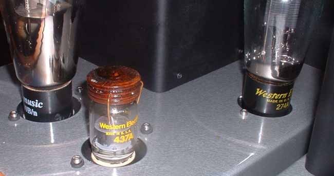
The circuit suits a wide range of triodes and triode-connected pentodes, for example:
- Triodes: WE 437A, WE 417A, STC 3A/167M, EC8010, EC8020, Reflektor 6S45-PE, Reflektor 6S4-PE, Reflektor 6S3-PE.
- Pentodes, triode-connected: E810F/7788, E280F/7722, E282F, E180F/6688, E55L/8233, D3a/7721.
The list is by no means complete.
Coupling the driver to the output valve
To couple the driver stage to the output stage I ended up with a mixture of methods best described as “baroque”. In principle, an interstage transformer would be ideal, but making one with enough bandwidth is no small matter. After many experiments in many other amplifiers, these conditions emerged for getting the best sound out of a triode driver stage.
First, the anode load should be a constant-current source or an anode choke. In repeated tests the anode choke was strongly preferred over most published current sources. Some published transistor current sources even did worse than a plain resistor in long-term listening, despite clearly audible and measurable advantages in some aspects of the sound. A hybrid current source with a J-FET and a pentode (2SK147 and E810F) sounded excellent, but was hard to fit into the existing chassis, and in the end subjectively lost to a specially designed anode choke.
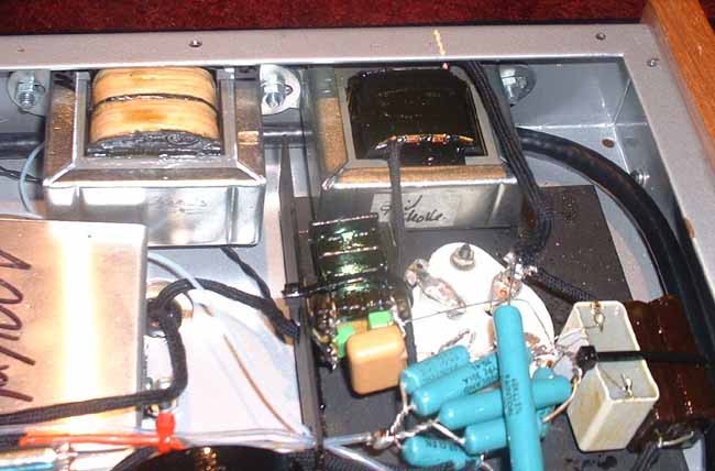
This anode choke has “pinstripe” laminations of nickel and M4 steel (one nickel lamination, one steel, one nickel, and so on), an extremely low self-capacitance (under 30 pF), and over 120 H of inductance at its nominal 12 mA DC. The exact inductance depends on frequency and level; at 1 V RMS and 10 Hz about 180 H can be measured. The DC resistance is about 1,200 Ohm. At 20 Hz and 1 V RMS the impedance is about 20 kOhm, at 1 kHz about 750 kOhm.
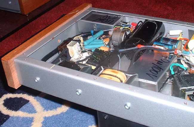
For the grid of the 300B, prompted by several sources but mainly by Gordon Rankin of Wavelength Audio, I tried a grid choke, and preferred it to a grid leak resistor. This choke is also wound for low self-capacitance and uses nickel laminations only. Depending on level and frequency, about 4,000 to 5,000 H can be measured. That gives an impedance of about 500 kOhm at 20 Hz, with about 1,000 Ohm DC resistance.
The exact reasons for the improvements the grid choke brings, objective (power output at high levels, overload behaviour) and subjective (much better dynamics and resolution), are unclear. With conventional coupling, a coupling capacitor and a 240 kOhm grid leak, grid current at high drive charges the coupling capacitor and produces a temporary extra negative bias on the grid. With music at high levels, that is in nominal overload, I measured up to about −20 V. With the grid choke, this unwanted negative grid voltage was limited to a few volts. This bias shift is a PTS: potential trouble source. A technical feature that can cause audible fidelity impairment while staying invisible to the usual FOMs, unless the design addresses it. The Audio Heretick's Progress: the FOM and PTS →: a steady-state THD measurement never shows it.
I would further theorise that the grid choke stores some magnetic energy, which it can release briefly when the grid is driven positive, a kind of inductive flywheel effect. How far all these effects, and others, play a part is pure speculation. Empirically, though, the grid choke was preferred to a grid leak resistor.
The coupling element between the driver anode and the output valve’s grid is, of course, a capacitor. Over the years I have tested many a capacitor, including plenty of boutique ware, and found most of them heavily coloured. Their strong “sound of their own” is surely one reason for their popularity: the difference is large, and if you can hear a difference and paid a lot of money, it must be an improvement…
In my experience the best coupling capacitors are silver mica types. The likely reason is their lack of microphony, which can be quite drastic, especially in metallised film capacitors. Second best are tin-foil and polypropylene capacitors (those sold as Angela, Audyn, M-Cap Zn and others, made by SCR, or the very expensive ones from MIT and REL). When pennies count, Arcotronics, LCR or Wima KP/FKP types (or antique ERO KP1832) are my preference. The much-praised oil-and-paper types do not go into my equipment, and various very expensive film or film-and-foil types are at best as good as the quite cheap Arcotronics KP1.72 series from RS Components.
With the driver circuit practically complete, a rather drastic resonance at very low frequencies was predictable (from the model) and also clearly measurable. A suitably chosen resistor in parallel with the grid choke flattened the bass response of the amplifier in the end. Some lift of the lowest frequencies in the driver stage was kept on purpose: at least at small signal levels, it compensates for the bass roll-off caused by the limits of the output stage and output transformer.
The driver operating point
After many trials the WE 437A settled at about 12 mA and 170 V on the anode (so 2.8 V cathode bias in this circuit). With all the high-transconductance triodes I have tried in this and other amplifiers and preamplifiers, the subjectively best sound came at comparatively low anode current. At high anode current the sound becomes glaring and unpleasant. The objective mechanisms are unclear, but subjectively the findings were quite consistent. At this operating point the driver has an anode impedance of about 2 kOhm and runs at about 30 % of its permitted dissipation, which should ensure a long life. With other valve types, first adjust the cathode resistor so the anode voltage is about 150 to 200 V. The exact value is best found by experiment and comparative listening.
The driver’s cathode bypass capacitor is a home-made “block”: five Evox Rifa 22 µF/63 V MKS capacitors placed in a small aluminium box, wired up and potted in wax. This block capacitor is easy to use and sounds excellent, especially for microphony, and is far superior to every electrolytic on the market, regardless of price.
The driver’s anode supply is decoupled with one of three 47 µF/450 V MKP capacitors (the other two are in the main power supply). These are potted in metal cans, made specially by Ansar, with silver leads.
The input
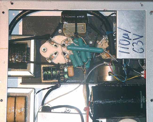
At the input of the driver stage, a Stevens & Billington TX-905 transformer serves both for matching and as a grid choke that stabilises the driver’s operating point. The 437A was really designed for grounded-grid operation: with too high a DC resistance from grid to ground, its operating point tends to run away. The transformer also allows a galvanically isolated, transformer-coupled balanced input.
The input transformer also limits the bandwidth of the signal passed on to the amplifier and is in practice the element that sets the bandwidth. Slew-rate limiting between the stages and in the output transformer therefore becomes impossible. Such effects normally cause strong transient intermodulation distortion (yes, even without loop feedback). They are easy to spot on an oscilloscope: as the frequency of a sine wave rises, often far above the nominal −3 dB point, the waveform does not just fall in level, it turns from a sine into a triangle.
The connection between the input sockets and the transformer is cable-TV cable with the centre conductor pulled out. This cable has a 100 % copper-foil screen plus a copper braid. With the centre conductor removed, six air cells remain. These guide and insulate the silver wires; the balanced and unbalanced inputs run together. The cable screen is connected to the same 25 V point that biases the 437A heater positive. This reduces MDI interference (see Pierre Johannet).
For stable operation, the 437A heater is also balanced (through a matched pair of 470 Ohm resistors) and raised to about 25 V above ground. This reverse-biases the parasitic diode between cathode and heater (cathode as the parasitic anode, heater as the parasitic cathode), so no parasitic conduction from the heater into the cathode, and so into the signal path, can occur. Two 1 nF ceramic capacitors ground the heater at high frequencies. This is strongly recommended with all high-transconductance valves; it reduces their built-in tendency to oscillate considerably.
The output stage
The 300B runs with cathode bias, and the way the bias is generated is worth a mention. On each side of the filament there is a resistor combination. Both are adjusted so that practically the same DC flows to ground from either “end” of the filament. As one end sits about 5 V higher, the resistor on that side is a little larger. This minimises the uneven cathode wear otherwise seen with DC heating.
The effective load for the valve is about 4,500 to 5,000 Ohm with this output transformer and the roughly 12 Ohm speaker impedance (the typical minimum impedance of a Tannoy Monitor Red). The operating point of 350 V/60 mA was chosen to produce a particular harmonic spectrum with these output transformers and speakers. It partly cancels the second-harmonic distortion of the speaker, so that at normal levels and in the critical (formant) range, the total distortion of the system is lower than a completely distortion-free amplifier could achieve. Measured alone, the amplifier’s THD, a FOM: figure of merit. A single number, such as THD+N, SINAD or jitter in picoseconds, used to sum up signal fidelity, with the claim that a better number means better sound. It relates to audible fidelity only at the extremes. The Audio Heretick's Progress: the FOM →, looks worse for it; the system as heard has better audible fidelity.
A pair of resistors in the cathode circuit provides a virtual centre tap of the filament, to which the cathode bypass combination connects. This combination holds further tricks, straight from the Western Electric books of the 1930s. 70 µF from cathode to ground and 20 µF from cathode to the supply rail form a frequency-independent voltage divider, which feeds a precisely calculated share of the noise on the supply rail into the cathode. Amplified by the output valve, it moves the anode by just the right amount for the noise to cancel across the output transformer.
Between cathode and supply rail sits an Ansar 20 µF/630 V MKP in a metal can, further bypassed with an ERO KP1832 0.075 µF/800 V, an ERO KP1832 3,600 pF/1,200 V, an NFS Styroflex 2,700 pF/500 V and a Lemo silver mica 2,200 pF/500 V. The cathode capacitor is a home-made block of seven Evox Rifa 10 µF/100 V MKS capacitors in an aluminium case, potted in wax.
In this amplifier, by the way, the noise on the supply rail comes less from mains hum than from the output stage modulating the supply. This trick improves the rejection of supply noise by up to about 30 dB. The resistor between the supply and the output stage adds some positive feedback, which, much like the “mixed feedback” method, reduces distortion in the output transformer and compensates for its DC resistance, at low frequencies only, of course.
A further bonus shows up if you work out the complex impedances of the output stage’s current loops and follow where the signal currents go. Down to fairly low frequencies (above 200 Hz, 70 % or more of it), the output signal current flows in the short loop from the cathode through the 20 µF capacitor, the output transformer and the valve. That is preferable both aesthetically and for the sound.
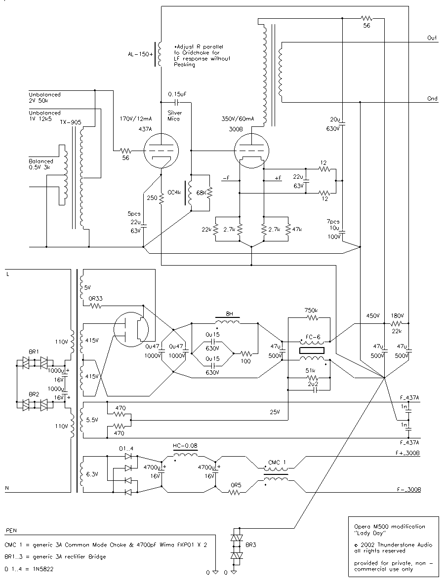
The diagram below shows the complete circuit of one monoblock, leaving out the specific connectors. The power supply is included, and the drawing also tries, as far as possible, to show the particular grounding and wiring.
The power supply
The rest of the amplifier is simply the power supply. As an amplifier is in the end only a modulated power supply, real care and effort must go in here.
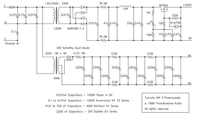
As mentioned, electrolytic capacitors were excluded, except for the 300B heater supply, because of their many substantial drawbacks: poor long-term stability, non-linearity, excessive parasitic inductance, microphony. The supply was also completely redesigned. A “tuned” first choke (tuned as a 100 Hz trap) is combined with a very small reservoir capacitor: a pair of 0.47 µF/1,000 V Arcotronics KP1.72 film-and-foil capacitors, 0.94 µF in total. These were chosen at least partly for their speed (high slew rate), which shorts out any high-frequency noise. The result is a supply with relatively small current pulses and inrush currents for the valve rectifier, and a somewhat lower anode voltage. The lower voltage is welcome, because the output stage runs at a moderate 350 V/60 mA instead of the original 400 V/80 mA.
The WE 274A rectifier was chosen for the same pragmatic reasons as the WE 437A driver: I had it on the shelf, and the 274A has a (well-deserved) reputation for good sound. With an octal socket, a 5U4 or 5R4 can be used, as can a GZ34/5AR4 and even a GZ32. I prefer brown-base RCA 5R4GY coke-bottles or Mullard GZ32s over other types; I tried them with octal-to-UX4 adapters. The WE 274A has a “nicer” and “airier” sound, though.
Between the three rectifiers (5R4, GZ32, 274A) the differences in operating point were minimal, so I am inclined to put the differences in sound down to other effects.
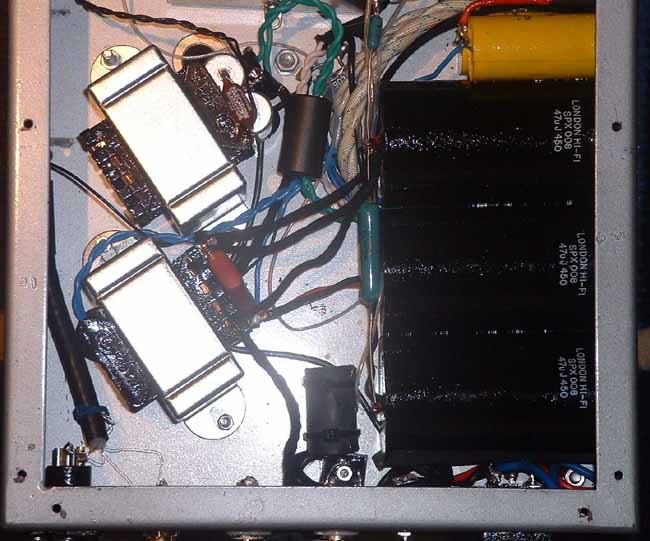
Because the 47 µF supply filter capacitors are on the small side (if of very high quality), a second LC filter cell was added. The second choke is designed for minimum self-capacitance and wound in two halves: one half sits in the negative lead, the other in the positive lead between the first and second filter capacitors. This improves the rejection of mains noise, which could otherwise find its way into the output stage’s ground and so into the system as noise current. The 100 Hz ripple is below 0.5 mV on the second filter capacitor and about 100 mV on the first.
With directly heated valves the cathode is also the heater, so the heater must get clean DC. The original circuit had about 300 mV RMS of noise on it, with a rather lively spectrum, further enriched by diode switching noise. Leakage currents in the heater winding can also reach the cathode-grid circuit, where they effectively become input signal for the output valve. High-frequency noise is not audible directly, but its intermodulation products with the signal fall back into the audio band, where they often audibly impair the sound. The subjective effect is often described as washed-out tone colours, a veil, and so on. Another PTS: potential trouble source. A technical feature that can cause audible fidelity impairment while staying invisible to the usual FOMs, unless the design addresses it. The Audio Heretick's Progress: the FOM and PTS →: an audio-band noise figure does not show it.
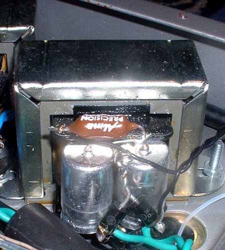
In the new 300B filament supply, switching-noise-free (Schottky) diodes feed moderate values of long-life electrolytic capacitors. A filter choke of about 80 mH, again designed for low self-capacitance, brings the 100 Hz differential ripple on the 300B filament down to about 10 mV, about 30 dB better than the original. Higher-frequency noise is very effectively suppressed. An additional common-mode choke, and a 22 µF MKS capacitor across the filament, make for an exemplary low-impedance filament supply, free of common-mode and differential noise.
DC on the mains
The power supply uses a toroidal transformer, and for a toroid to work properly, any DC component on the mains must be blocked. This DC is usually caused by the 10 to 20 % second-harmonic distortion of the mains waveform found on most grids. On my mains I can measure up to 1 V of fluctuating DC, depending on the time of day. With a primary DC resistance of about 5 Ohm, that means up to about 200 mA of DC, which pre-magnetises the gapless core of the transformer, causing both mechanical hum and a much reduced efficiency.
The blocking circuit sits in the link between the two halves of the primary winding and can block up to 2.4 V of DC on the mains. It consists of two diode bridges, each with its + and − outputs shorted and the AC terminals in series, plus two low-impedance, long-life electrolytic capacitors connected as a non-polar pair. The diodes block DC (up to about 2.4 V, the threshold of four silicon diodes in series) and let AC pass.
These parts carry mains voltage, so take the utmost care when building it. Make sure (with additional insulation and so on) that they cannot touch any other part, and that even with the case open, the chance of accidentally touching a live part is minimised.
Ground loops
Another “trick” sits in the grounding of the signal circuit. A further bridge rectifier, again with its + and − outputs shorted, is connected between the signal ground and the protectively earthed case. Because of the high voltages inside, the signal ground MUST be earthed, for electrical safety. That can cause unwanted ground loops, though. The diode bridge interrupts the current between chassis/protective earth and signal ground as long as the peak voltage stays below 1.2 V, which breaks practically all normal ground loops. If the voltage rises above 1.2 V, the diodes conduct, fault currents are carried away, and fault voltages are limited to about 2.2 V at most.
Note that the TÜV and similar organisations have no official guidelines allowing this. Testing a device wired this way for electrical safety, the testers available to me (the usual pass/fail types) show the loop resistance as “good”, with the necessary exception of the RCA socket, where the 0.07 mm ground wire gives a “bad” reading.
Measurements and use
Finally: in the finished amplifier the measurable noise at the output is below 0.1 mV, and it is pure 50 Hz, magnetic fields picked up by the chokes in the driver stage. Into a nominal 16 Ohm load, 4 V corresponds to 1 W. The maximum level for under 3 % THD is a little over 10 V (measured at 1 kHz). So about 7 W RMS at under 3 % THD is available, with an unweighted signal-to-noise ratio of 100 dB referred to full power. At about 1 W the frequency response is 10 Hz to 35 kHz (−1 dB, +0 dB) into a resistive load. THD is then about 0.5 %, practically pure second harmonic.
With efficient 15 Ohm speakers (Tannoy Monitor Red 15 inch, 95 dB/2.83 V/1 m), the amplifier can handle any musical material without subjective limits or distortion. That includes large symphonic works at close to original level (and far beyond the “good neighbour” threshold), and hard rock and heavy metal at Spinal Tap settings.
The figures above are FOM: figure of merit. A single number, such as THD+N, SINAD or jitter in picoseconds, used to sum up signal fidelity, with the claim that a better number means better sound. It relates to audible fidelity only at the extremes. The Audio Heretick's Progress: the FOM → and tell only the signal fidelity part of the story, nothing about audible fidelity; the design was decided by comparative listening in addition to measurements.
All the additional chokes were developed with Stevens & Billington. Ansar capacitors were hard to get at the time, with long delivery times. Other good makes of encapsulated metallised polypropylene capacitors can be used without problems.